


Controller Inputs and Outputs
ESIE10-01
3–58
3
1
3
4
5
2.3
Expansion I/O Compressor #1 to #4 (POL965.00/MCQ)
Analog inputs
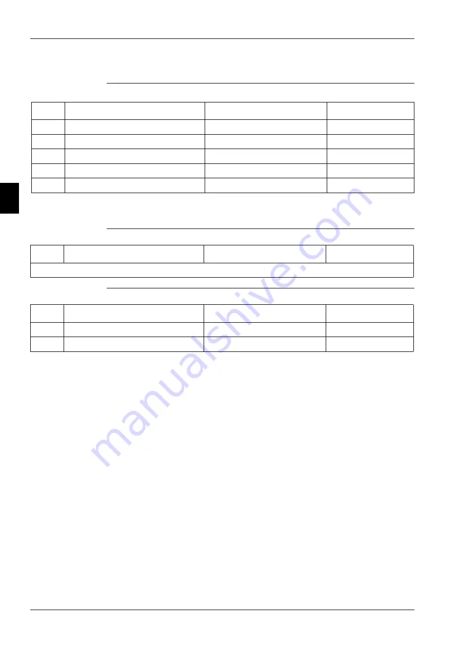
Note:
X7 is configured the same regardless of Manufacturing Location. However, for U.S. chillers the
signal source is a digital input so the control logic must account for this.
Analog outputs
Digital inputs
#
Description
Signal Source
Expected Range
X1
Discharge Temperature
NTC Thermister (10K@25°C)
-50°C – 120°C
X2
Evaporator Pressure
Ratiometric (0,5-4,5 Vdc)
0 to 5 Vdc
X3
Oil Pressure
Ratiometric (0,5-4,5 Vdc)
0 to 5 Vdc
X4
Condenser Pressure
Ratiometric (0,5-4,5 Vdc)
0 to 5 Vdc
X7
Motor Protection
NTC Thermister (10K@25°C)
n/a
#
Description
Output Signal
Range
Not Needed
#
Description
Signal Off
Signal On
X6
Starter Fault
Fault
No fault
DI1
High Pressure Switch
Fault
No fault
Содержание EWAD620-C17C-SS
Страница 2: ......
Страница 8: ...ESIE10 01 1 2 Part 1 System Outline 3 1 1 5...
Страница 111: ...ESIE10 01 General Outline Part 1 System Outline 1 105 3 1 4 5 1 36 1 Power Compressor 1 2...
Страница 112: ...General Outline ESIE10 01 1 106 Part 1 System Outline 3 1 1 4 5 1 36 2 Power Compressor 3...
Страница 113: ...ESIE10 01 General Outline Part 1 System Outline 1 107 3 1 4 5 1 36 3 Kit Pumps...
Страница 114: ...General Outline ESIE10 01 1 108 Part 1 System Outline 3 1 1 4 5 1 36 4 Circuit Fan Power Supply 1...
Страница 115: ...ESIE10 01 General Outline Part 1 System Outline 1 109 3 1 4 5 1 36 5 Circuit Fan Power Supply 1...
Страница 116: ...General Outline ESIE10 01 1 110 Part 1 System Outline 3 1 1 4 5 1 36 6 Circuit Fan Power Supply 2...
Страница 117: ...ESIE10 01 General Outline Part 1 System Outline 1 111 3 1 4 5 1 36 7 Circuit Fan Power Supply 2...
Страница 118: ...General Outline ESIE10 01 1 112 Part 1 System Outline 3 1 1 4 5 1 36 8 Circuit Fan Power Supply 3...
Страница 119: ...ESIE10 01 General Outline Part 1 System Outline 1 113 3 1 4 5 1 36 9 Circuit Fan Power Supply 3...
Страница 120: ...General Outline ESIE10 01 1 114 Part 1 System Outline 3 1 1 4 5 1 36 10 Unit Control Circuit Power Supply...
Страница 121: ...ESIE10 01 General Outline Part 1 System Outline 1 115 3 1 4 5 1 36 11 Analog Inputs Output Board...
Страница 122: ...General Outline ESIE10 01 1 116 Part 1 System Outline 3 1 1 4 5 1 36 12 Digital Inputs Board...
Страница 123: ...ESIE10 01 General Outline Part 1 System Outline 1 117 3 1 4 5 1 36 13 Digital Outputs Board...
Страница 124: ...General Outline ESIE10 01 1 118 Part 1 System Outline 3 1 1 4 5 1 36 14 Digital Outputs Board...
Страница 125: ...ESIE10 01 General Outline Part 1 System Outline 1 119 3 1 4 5 1 36 15 Extension Control Fans 1 2...
Страница 126: ...General Outline ESIE10 01 1 120 Part 1 System Outline 3 1 1 4 5 1 36 16 Extension Control Fans 3...
Страница 127: ...ESIE10 01 General Outline Part 1 System Outline 1 121 3 1 4 5 1 36 17 Extension Control Fans 4...
Страница 128: ...General Outline ESIE10 01 1 122 Part 1 System Outline 3 1 1 4 5 1 36 18 Expansion Input Output Unit Alarm Limiting...
Страница 129: ...ESIE10 01 General Outline Part 1 System Outline 1 123 3 1 4 5 1 36 19 Expansion Control Compressor 1...
Страница 130: ...General Outline ESIE10 01 1 124 Part 1 System Outline 3 1 1 4 5 1 36 20 Expansion Control Compressor 1...
Страница 131: ...ESIE10 01 General Outline Part 1 System Outline 1 125 3 1 4 5 1 36 21 EEXV Compressor 1...
Страница 132: ...General Outline ESIE10 01 1 126 Part 1 System Outline 3 1 1 4 5 1 36 22 Expansion Control Compressor 2...
Страница 133: ...ESIE10 01 General Outline Part 1 System Outline 1 127 3 1 4 5 1 36 23 Expansion Control Compressor 2...
Страница 134: ...General Outline ESIE10 01 1 128 Part 1 System Outline 3 1 1 4 5 1 36 24 EEXV Compressor 2...
Страница 135: ...ESIE10 01 General Outline Part 1 System Outline 1 129 3 1 4 5 1 36 25 Expansion Control Compressor 3...
Страница 136: ...General Outline ESIE10 01 1 130 Part 1 System Outline 3 1 1 4 5 1 36 26 Expansion Control Compressor 3...
Страница 137: ...ESIE10 01 General Outline Part 1 System Outline 1 131 3 1 4 5 1 36 27 EEXV Compressor 3...
Страница 138: ...General Outline ESIE10 01 1 132 Part 1 System Outline 3 1 1 4 5 1 36 28 Pumps Control...
Страница 139: ...ESIE10 01 General Outline Part 1 System Outline 1 133 3 1 4 5 1 36 29 Terminals M1 M2...
Страница 140: ...General Outline ESIE10 01 1 134 Part 1 System Outline 3 1 1 4 5 1 36 30 Terminals M3...
Страница 141: ...ESIE10 01 General Outline Part 1 System Outline 1 135 3 1 4 5 1 36 31 Terminals M5 MQ...
Страница 148: ...General Outline ESIE10 01 1 142 Part 1 System Outline 3 1 1 4 5...
Страница 150: ...ESIE10 01 2 2 Part 2 Functional Description 3 1 2 5...
Страница 170: ...The Digital Controller ESIE10 01 2 22 Part 2 Functional Description 3 1 2 4 5...
Страница 200: ...Functional Control ESIE10 01 2 52 Part 2 Functional Description 3 1 2 4 5...
Страница 202: ...ESIE10 01 3 2 Part 3 Troubleshooting 3 1 3 5...
Страница 254: ...Alarms and Events ESIE10 01 3 54 Part 3 Troubleshooting 3 1 3 4 5...
Страница 266: ...Controller Inputs and Outputs ESIE10 01 3 66 Part 3 Troubleshooting 3 1 3 4 5...
Страница 280: ...ESIE10 01 4 2 Part 4 Commissioning and Test Run 3 1 4 5...
Страница 286: ...Pre Test Run Checks ESIE10 01 4 8 Part 4 Commissioning and Test Run 3 1 4 5...
Страница 289: ...ESIE10 01 Running Data Part 4 Commissioning and Test Run 4 11 3 4 5 1...
Страница 290: ...Running Data ESIE10 01 4 12 Part 4 Commissioning and Test Run 3 1 4 5...
Страница 292: ...ESIE10 01 5 2 Part 5 Maintenance 3 1 5...


