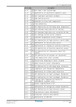
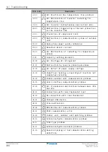


16
|
Technical data
Installer reference guide
255
EPRA14~18D + ET23E
Daikin Altherma 3 H HT F
4P644739-1A – 2022.03
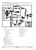
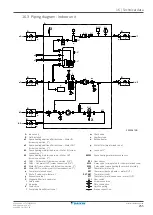
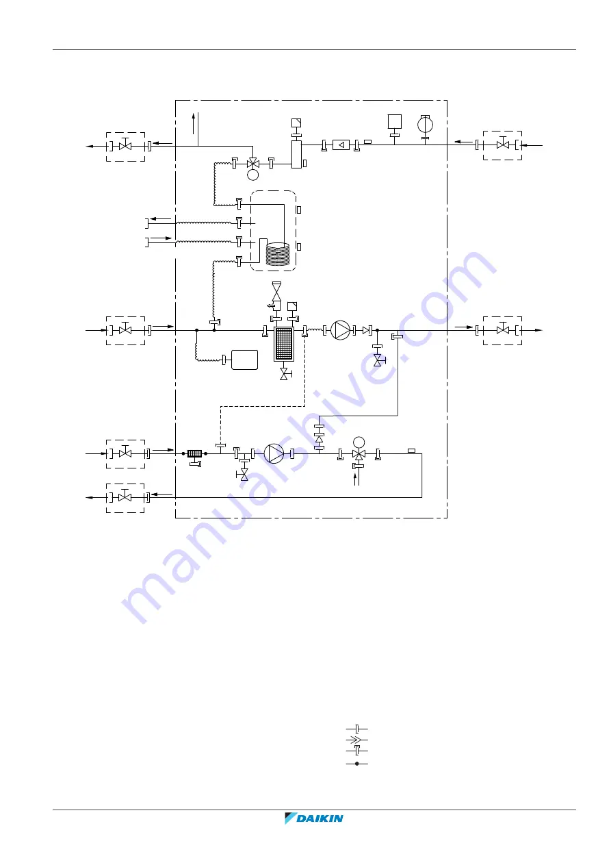
16.3 Piping diagram: Indoor unit
3D120612B
B1PW
S1L
M3S
M1S
R8T
R2T
R1T
R5T
R7T
A
B
B
l
m
m
a2
a1
d2
d1
c2
c1
g
h
k
k
i
j
B2L
o
j
f
B
b1
f
f
B
b2
f
q
q
q
q
q
q
M
M
X
X
k
p
n
e
B
f
B
f
A
Indoor unit
m
Check valve
B
Field installed
n
Capillary tube
a1
Space heating additional/direct zone – Water IN
(screw connection, 1")
o
Backup heater
a2
Space heating additional/direct zone – Water OUT
(screw connection, 1")
p
Water filter (main/mixed zone)
b1
Space heating main/mixed zone – Water IN (screw
connection, 1")
q
Loose nut 1"
b2
Space heating main/mixed zone – Water OUT
(screw connection, 1")
B1PW
Space heating water pressure sensor
c1
DHW – Cold water IN (screw connection, 3/4")
B2L
Flow sensor
c2
DHW – Hot water OUT (screw connection, 3/4")
M1S
3-way valve (mixing valve for the main/mixed zone)
d1
Water IN from outdoor unit (screw connection, 1")
M3S
3-way valve (space heating/domestic hot water)
d2
Water OUT to outdoor unit (screw connection, 1")
R1T
Thermistor (water IN)
e
Pump (main/mixed zone)
R2T
Thermistor (backup heater – water OUT)
f
Shut-off valve, male-female 1"
R5T, R8T
Thermistor (tank)
g
Expansion vessel
R7T
Thermistor (main/mixed zone – water OUT)
h
Magnetic filter/dirt separator
S1L
Flow switch
i
Safety valve
Screw connection
j
Air purge
Flare connection
k
Drain valve
Quick coupling
l
Pump (additional/direct zone)
Brazed connection
Содержание ETVZ16E6V7
Страница 281: ......
Страница 282: ......
Страница 283: ......
Страница 284: ...4P644739 1A 2022 03 Copyright 2021 Daikin Verantwortung f r Energie und Umwelt...


