4 Unit installation
Installation manual
13
EL23E
Daikin Altherma 3 R MT F
4P708476-1 – 2023.03
4×
T25
4
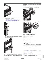
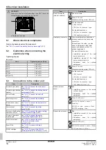
If necessary, remove the front plate. This is, for example,
necessary in the following cases:
▪
"4.2.2 To lower the switch box on the indoor unit"
▪
"4.3.2 To connect the drain hose to the drain"
▪ When you need access to the high voltage switch box
2×
T25
5
If you need access to the high voltage components, remove the
high voltage switch box cover.
4×
T25
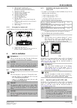
4.2.2
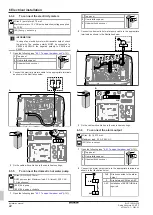
To lower the switch box on the indoor unit
During the installation, you will need access to the inside of the
indoor unit. To have easier front access, put the switch box lower on
the unit as follows:
Prerequisite:
The user interface panel and front panel have been
removed.
1
Remove the fixing plate at the top of the unit.
2
Tilt the switch box to the front and lift it out of its hinges.
1
2
2×
T25
3
Place the switch box lower on the unit. Use the 2 hinges located
lower on the unit.
3
3
4.2.3
To close the indoor unit
1
Close the cover of the switch box.
2
Put the switch box back into place.
3
Reinstall the top panel.
4
Reinstall the side panels.
5
Reinstall the front panel.
6
Reconnect the cables to the user interface panel.
7
Reinstall the user interface panel.
NOTICE
When closing the indoor unit cover, make sure that the
tightening torque does NOT exceed 4.1 N•m.
4.3
Mounting the indoor unit
4.3.1
To install the indoor unit
1
Lift the indoor unit from the pallet and place it on the floor. Also
see
"3.1.2 To handle the indoor unit"
5].
2
Connect the drain hose to the drain. See
3
Slide the indoor unit into position.
4
Adjust the height of the leveling feet to compensate for floor
irregularities. The maximum allowed deviation is 1°.
Содержание ELVZ-E9W
Страница 45: ......
Страница 46: ......
Страница 47: ......
Страница 48: ...4P708476 1 2023 03 Copyright 2023 Daikin 4P708476 1 0000000U Verantwortung f r Energie und Umwelt...

