6 Electrical installation
Installation manual
24
EL23E
Daikin Altherma 3 R MT F
4P708476-1 – 2023.03
A
1
2
4
5
S6S
S7S
S8S
S9S
3
B
A
B
A8P
X801M
1
2
3
4
5
a
a
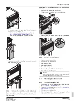
Installation of EKRP1AHTA (+ mounting plate, see
"6.4 To install the mounting plate"
27]) is required.
3
Fix the cable with cable ties to the cable tie mountings.
6.3.9
To connect the safety thermostat
(normally closed contact)
1
Open the following (see
"4.2.1 To open the indoor unit"
12]):
1
Top panel
1
2
3
2
User interface panel
3
Upper switch box cover
Main zone
Wires: 2×0.75 mm²
—
2
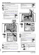
Connect the safety thermostat (normally closed) cable to the
appropriate terminals as shown in the illustration below.
A
2
Q3L
1
B
A
B
X5M
1 2
3
Fix the cable with cable ties to the cable tie mountings.
INFORMATION
Installation of a safety thermostat (field supply) is required
for the main zone, otherwise the unit will NOT operate.
NOTICE
A safety thermostat MUST be installed on the main zone to
avoid too high water temperatures in this zone. The safety
thermostat is typically a thermostatically controlled valve
with a normally closed contact. When the water
temperature in the main zone is too high, the contact will
open and the user interface will show a 8H‑02 error. ONLY
the main pump will stop.
Additional zone
Wires: 2×0.75 mm²
Maximum length: 50 m
Safety thermostat contact: 16 V DC detection (voltage
supplied by PCB). The voltage-free contact shall ensure the
minimum applicable load of 15 V DC, 10 mA.
—
4
Connect the safety thermostat (normally closed) cable to the
appropriate terminals as shown in the illustration below.
Note:
The jumper wire (factory-mounted) must be removed from the
respective terminals.
Содержание ELVZ-E9W
Страница 45: ......
Страница 46: ......
Страница 47: ......
Страница 48: ...4P708476 1 2023 03 Copyright 2023 Daikin 4P708476 1 0000000U Verantwortung f r Energie und Umwelt...


