background image

31

Troubleshooting

Restore factory settings

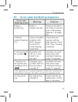
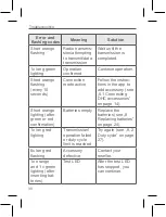
Error and 

flashing codes

Meaning

Solution

Short orange 

flashing

Radio transmis-

sion/attempting 

to transmit/data 

transmission

Wait until the 

transmission is 

completed.

1x long green 

lighting

Operation 

confirmed

Continue operation.

Short orange 

flashing 

(every 10 

seconds)

Connection 

mode active

Follow the instruc-

tions in the app to 

add accessory (see 

„5.1 Connecting 

DHC accessories“ 

on page 14).

Short orange 

lighting (after 

green or red 

confirmation)

Batteries empty Replace the 

batteries (see „8 

Replacing batteries“ 

on page 24).

1x long red 

lighting

Transmission/

operation failed 

or duty cycle 

limit is reached

Try again (see. „9.2 

Duty cycle“ on page 

27).

6x long red 

flashing

Accessory 

defective

Contact your 

reseller.

1x orange 

and 1 x green 

lighting (after 

inserting bat-

teries)

Test LED

After the test LED 

has stopped, you 

can continue.

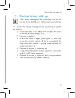
10  Restore factory settings

The factory settings of the accessory can be re-

stored. If you do this, you will lose all your settings.

To restore the factory settings of the accessory, proceed 

as follows:

1.  Grab the sides of the electronic unit 

(B)

 and pull it 

out of the frame 

(see figure 6)

.

2.  Remove a battery.

3.  Insert the battery again (

see  figure  7

) and long 

press the system button 

(D)

 for 4 seconds at the 

same time until the LED quickly starts flashing or

-

ange (

see figure 8)

.

4.  Release the system button again.

5.  Long press the system button again for 4 seconds, 

until the LED lights up green.

6. 

Release the system button to finish the procedure.


» The accessory will perform a restart.

Содержание EKRCTRDI3BA

Страница 1: ...Installer and user reference guide Daikin Home Controls Room Thermostat 2 EKRCTRDI3BA...

Страница 2: ...2 1 A F C D E B...

Страница 3: ...4 3 G H I J I J...

Страница 4: ...6 5 K...

Страница 5: ...8 7...

Страница 6: ...r may it be duplicated or edited by electronic mechanical or chemical means without the written consent of the publisher Typographical and printing errors cannot be excluded However the information co...

Страница 7: ...5 2 Mounting 16 5 2 1 Adhesive strip mounting 16 5 2 2 Screw mounting 17 5 2 3 Flush mounted box mounting 18 6 Configuration 20 6 1 Automatic mode 21 6 2 Manual mode 21 6 3 Holiday mode 21 6 4 Operati...

Страница 8: ...b 2 9 Troubleshooting 27 9 1 Weak battery 27 9 2 Duty cycle 27 9 3 Error codes and flashing sequences 29 10 Restore factory settings 31 11 Maintenance and cleaning 32 12 General information about radi...

Страница 9: ...to other persons for use hand over this manual as well Symbols used Attention This indicates a hazard Please note This section contains important additional informa tion 2 Hazard information Do not o...

Страница 10: ...ssume any liability for damage to prop erty or personal injury caused by improper use or the failure to observe the hazard information In such cases any claim under warranty is extin guished For conse...

Страница 11: ...HC ecosystem and commu nicates with a dedicated wireless connection All accessories of the system can be configured comfort ably and individually via the ONECTA app The available functions provided by...

Страница 12: ...idity and transmits these at intervals to the DHC Radiator Thermostats or DHC Floor Heating Control lers enabling room temperatures to be precisely controlled You can comfortably control the DHC Room...

Страница 13: ...n pp he clip e DHC Display overview see figure 2 Setpoint actual temperature Humidity Warning about condensation Open window symbol Battery symbol Radio transmission Boost function Manual mode Automat...

Страница 14: ...nection to other DHC accessories For further information on direct connection see the DHC Application Guide 5 1 1 Connecting to the DHC Access Point First set up your DHC Access Point via the ONECTA a...

Страница 15: ...t and pull it from the mounting plate see figure 6 6 Turn over the electronic unit B 7 Remove the insulation strip from the battery com partment Connection mode remains activated for 3 minutes You can...

Страница 16: ...an use the supplied double sided adhesive strips or the supplied screws You can also mount the DHC Room Thermostat on a flush mounted box 5 2 1 Adhesive strip mounting To mount the DHC Room Thermostat...

Страница 17: ...ess the assembled DHC Room Thermostat with the back side to the wall 5 2 2 Screw mounting For mounting the DHC Room Thermostat with screws pro ceed as follows 1 Choose a site for installation Make sur...

Страница 18: ...on the back side point upwards and that the clips on the mounting plate latch into the openings on the electronic unit 5 2 3 Flush mounted box mounting You can mount the DHC Room Thermostat on a flus...

Страница 19: ...trical installer Specialist knowledge required for installation The following specialist knowledge is particularly important during installation The 5 safety rules to be used Disconnect from mains Saf...

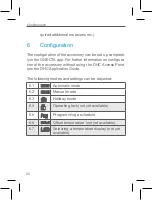
Страница 20: ...ee the DHC Application Guide The following modes and settings can be adjusted 6 1 Automatic mode 6 2 Manual mode 6 3 Holiday mode 6 4 Operating lock not yet available 6 5 Programming a schedule 6 6 Of...

Страница 21: ...dance with the current temperature set via the control wheel E The temperature remains activated until the next manual change 6 3 Holiday mode Holiday mode can be activated in the ONECTA app It will p...

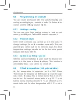
Страница 22: ...ted days for which temperature settings have to be set for the entire period between 00 00 and 23 59h 6 5 3 Optimum start stop function With the optimum start stop you can reach the desired tem peratu...

Страница 23: ...TA app and cannot be changed for the moment 6 7 Selecting a temperature display not yet available You can choose which temperature will be displayed on the accessory There are 3 options display the ac...

Страница 24: ...will be activated again In manual mode the temperature remains activated until the next manual change Boost function Press the control wheel E briefly to activate the boost function The boost functio...

Страница 25: ...and the arrows on the back side of the electronic unit point upwards and that the clips on the mounting plate latch into the openings on the electronic unit 5 Pay attention to the flashing signals of...

Страница 26: ...atteries should not be disposed of with reg ular domestic waste Instead take them to your lo cal battery disposal point 9 9 1 Provide will rem is low D to send have b If the v battery be disp flashing...

Страница 27: ...flashing sequences on page 29 In this case replace the empty batteries by two new batteries see 8 Replacing batteries on page 24 9 2 Duty cycle The wireless DHC accessories operate in the following fr...

Страница 28: ...with a duty cycle of respectively 1 and 10 During normal operation of the DHC accessories this limit is not usually reached However it is possible that the limit is reached during start up or during...

Страница 29: ...he con nection with the DHC Access Point DHC Floor Heating Controller Flashing humid ity symbol Humidity limit 60 in the room is ex ceeded Ventilate the room and switch from cooling to heating mode if...

Страница 30: ...n the app to add accessory see 5 1 Connecting DHC accessories on page 14 Short orange lighting after green or red confirmation Batteries empty Replace the batteries see 8 Replacing batteries on page 2...

Страница 31: ...follows 1 Grab the sides of the electronic unit B and pull it out of the frame see figure 6 2 Remove a battery 3 Insert the battery again see figure 7 and long press the system button D for 4 seconds...

Страница 32: ...xpert to car ry out any maintenance or repairs Clean the accessory using a soft lint free cloth that is clean and dry You may dampen the cloth a little with lukewarm water in order to remove more stub...

Страница 33: ...cal devices The range of transmission within buildings can dif fer greatly from that available in the open air Be sides the transmitting power and the reception characteristics of the receiver environ...

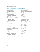
Страница 34: ...otection IP20 Ambient temperature 0 to 35 C Dimensions W x H x D Without frame 55 x 55 x 23 5 mm Including frame 86 x 86 x 25 mm Weight 100 g including batteries Radio frequency F1 868 3 MHz F2 869 52...

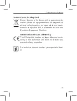
Страница 35: ...sposed of at local collection points for waste electronic equip ment in compliance with the Waste Electrical and Electronic Equipment Directive Information about conformity The CE sign is a free tradi...

Страница 36: ...Free download of the ONECTA app 4P687366 1 2022 04...

Отзывы: