- 8 -
All installation and management activities
must be carried out by qualified personnel.
Refer to the specific wiring diagram and
electrical component manual are attached
with the product before electrical
installation. Site contractor shall do
termination at site for wiring connection
between components that located at
different AHU sections and delivered
separately.
IMPORTANT
MAKE SURE ALL THE ELECTRIC
POWER
DISCONNECT
AND
SECURE
FROM
SWITCH
ON
BEFORE
DOING
WIRING
CONNECTION
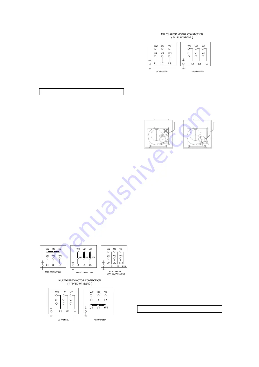
5.7.1 Motor Connection
The electric supply to the motor must
correspond to the rated voltage stated in
motor nameplate and be in conformance
with the National and Local Electric Code
and Regulations. Motor supplied able to
operate within 10% tolerance from the
nameplate voltage. Motor connection
details are contained in the cover of the
motor terminal box. (See Figure 22). The
fan section metal frame must be grounded.
Suitable electrical protection isolator
should be installed to protect the motor
and other electrical equipment.
Flexible conduit must be used when wiring
up fan motors to allow the fan motor to
move freely on its anti-vibration mounts.
Cables passing through panels must be
made with gland or grommet.
For inverter control, refer to the VFD
manual for wire size and requirements.
Figure 22 – 3 phases motor connection diagram
5.7.2 Motor Cabling
Motor wiring must go downward from
motor
terminal
box
to
prevent
condensation water flowing into motor
and lead to a failure. (See Figure 23)
Figure 23
–
Motor Cabling
5.8 Drive Belt & Sheave
Improper sheave alignment and belt
tension can cause excessive vibration,
premature failure of belts and bearings.
See Figure 24 for correct motor sheave
and fan sheave alignment.
Tensioning of the drive belt is achieved by
moving the motor in relation to the fan
(See Figure 25). When inserting new belts,
do not force belts over grooves, Loosen
the adjusting screw at motor base until
belt can slide smoothly over the grooves.
When all belts are in position, proceed to
adjust belt tension using the adjusting
screw and nuts on the motor base.
Use recognized belt tension gauge to
check the belt tension by apply a force
large enough at the center of the belt to
deflect the belt by 16mm per meter (See
Figure 26). The deflection force for any
belt should be within the minimum and
maximum force shown in table 1. Readjust
the tension to maximum value when it
drops to min. value. The deflection force
of factory setting is based on “Initial
Fitting”, re-tensioning as “Retension” after
the unit has run for 24 hours.
WARNING
OVER TENSION TOWARD DRIVE
BELT WILL CAUSE PREMATURE
FAILURE OF BELT AND BEARING
DAMAGE.


