16
MODEL
SHEAVE
DIAMETER
(in)
DEFLECTION
(in)
BELT
DRIVE
Used
New
15 Ton B, BA Standard 4.3 to 5.5
5.5
+
.5
8.2
+
.5
1/4 ± 1/16
20 Ton B, BA Standard 4.3 to 5.5
5.5
+
.5
8.2
+
.5
1/4 ± 1/16
25 Ton B, BA Standard 5.1 to 6.1
5.5
+
.5
8.2
+
.5
1/4 ± 1/16
DEFLECTION
FORCE (lbs)
TYPE
RECOMMENDED POUNDS OF FORCE PER BELT
When new V-belts are installed on a drive the initial tension will
drop rapidly during the first few hours. Check tension frequently
during the first 24 hours of operation. Subsequent retensioning
should fall between the minimum and maximum force. To de-
termine the deflection distance from the normal position, use a
straightedge or stretch a cord from sheave to sheave to use as a
reference line. On multiple belt drives, an adjacent undeflected
belt can be used as a reference.
MOTOR SHEAVE ADJUSTMENTS
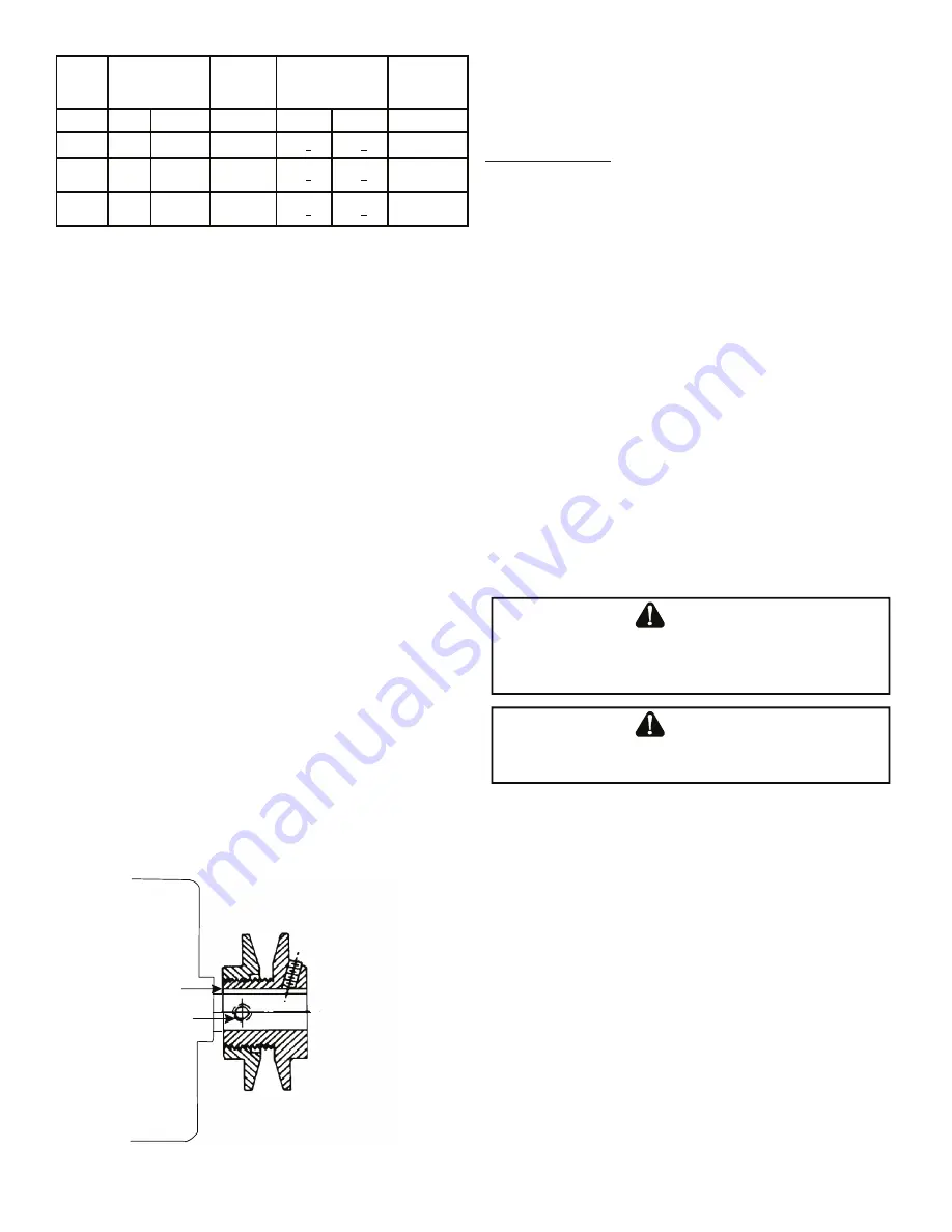
Vl, Vm & 2vp Variable Pitch Key Type Motor Sheaves
The driving and driven motor sheaves should be in alignment with
each other and the shafts parallel.
Vl & Vm Sheaves Adjustment
1. Loosen set screw “B” using a 5/32” Allen key.
2. Making half or full turns from closed position, adjust sheave
pitch diameter for desired speed. DO NOT OPEN MORE
THAN SIX FULL TURNS.
3. Tighten set screw “B” securely over flat.
4. Carefully put on belts and adjust belt tension. DO NOT
FORCE BELTS OVER GROOVES.
5. Ensure all keys are in place and the set screws tight before
starting drive. Recheck set screws and belt tension after
24 hours service.
NOTE:
Future adjustments should be made by loosening the belt
tension and increasing or decreasing the pitch diameter of the
sheave by half or full turns as required. Readjust belt tension before
starting drive.
C
B
VL & VM
NOTE:
Do not operate sheave with flange projecting beyond the
hub end.
GAS SYSTEM CHECK
Pre-Operation Checks
1. Close the manual gas valve external to the unit.
2. Turn off the electrical power supply to the unit.
3. Set the room thermostat to its lowest possible setting.
4. Remove the heat exchanger door on the side of the unit
by removing screws.
5. This unit is equipped with an ignition device which
automatically lights the main burner. DO NOT try to light
burner by any other method.
6. Move the gas control valve switch to the OFF position. Do
not force.
7. Wait five minutes to clear out any gas.
8. Smell for gas, including near the ground. This is important
because some types of gas are heavier than air. If you have
waited five minutes and you do smell gas, immediately
follow the warnings on page 3 of this manual. If having
waited for five minutes and no gas smell is noted, move
the gas control valve switch to the ON position.
9. Replace the heat exchanger door on the side of the unit.
10. Open the manual gas valve external to the unit.
11. Turn on the electrical power supply to the unit.
12. Set the thermostat to desired setting.
Gas Supply Pressures & Regulator Adjustments
S
HOULD
OVERHEATING
OCCUR
OR
THE
GAS
SUPPLY
FAIL
TO
SHUT
OFF
,
TURN
OFF
THE
MANUAL
GAS
SHUTOFF
VALVE
EXTERNAL
TO
THE
UNIT
BEFORE
TURNING
OFF
THE
ELECTRICAL
SUPPLY
.
WARNING
T
O
AVOID
PROPERTY
DAMAGE
,
PERSONAL
INJURY
OR
DEATH
,
DO
NOT
FIRE
GAS
UNIT
WITH
FLUE
BOX
COVER
REMOVED
.
WARNING
NOTE:
Except during brief periods when gas pressures are being
measured by qualified service personnel, the furnace access panel
must always be secured in place when the furnace is in operation.
An inspection port in the access panel is provided to monitor the
flame.
The first step in checking out the gas-fired furnace is to test the
gas supply piping to the unit for tightness and purge the system
of air using methods outlined in the latest edition of the National
Fuel Gas Code ANSI Z223.1. Verify that the disconnect switch is
in the “OFF” position. A soapy water solution should be used to
check for gas leaks. Since the unit is subject to considerable jarring
during shipment, it is extremely important that all gas connections
and joints be tested for tightness. Gas piping downstream from
the unit inlet should be checked for leaks during the subsequent
sequence check.
The supply gas pressure should be adjusted to 7.0” w.c. on natural
gas and 11.0” on LP gas with the gas burners operating. If there is
more than one unit on a common gas line, the pressures should
be checked with all units under full fire. A supply pressure tap is
Содержание DBG Series
Страница 29: ...29 APPENDIX D WIRING DIAGRAMS...
Страница 39: ...39 THIS PAGE INTENTIONALLY LEFT BLANK...


