


3
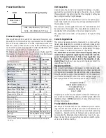
Product Identification
DAR
Nominal Cooling Capacity
Model Series
DAR
0904 - 90,000 Btuh (7 1/2 Tons)
1204 - 120,000 Btuh (10 Tons)
Product Description
When matched with DX11 and DZ11 condensers, this system com-
plies with the minimum efficiency requirements found in ASHRAE
90.1-2007. See the Daikin DX11 and DZ11 specification sheets for
details on these condensers. For other Daikin condenser(s) that
can be matched with this airhandler to obtain ASHRAE 90.1-2007
compliance, consult with your local distributor.
The DAR series is intended for use with a room thermostat. This
thermostat is not supplied with this equipment. Only thermostats
that use 24 VAC control circuitry are to be used.
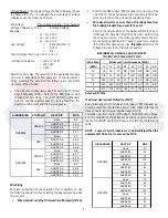
DAR0904
DAR1204
Net Weight (Lbs.)
375
400
Shipping Weight (Lbs.)
405
430
Refrigerant
R-410A
R-410A
Blower Wheel (Dia x Width)
11X10
11X10
Blower Wheel Quantity
2
2
Motor Type
Belt Drive
Belt Drive
Motor Qty
1
1
Motor (HP)
1 1/2
2
Motor (RPM)
1750
1750
Motor Sheave Type
Motor Sheave Diameter (in)
1.9" - 2.9"
2.8" - 3.8"
Blower Wheel Pulley Type
Blower Wheel Pulley Dia (in)
5.9
5.9
Evaporator Coil Material
Face Area (Ft
2
)
8.9
10.0
Number of Rows
4
4
Suction Line Quantity
1
2
Suction Line Connection (in) *
1 1/8
1 1/8
Liquid Line Quantity
1
2
Liquid Line Connection (in)*
5/8
3/8
Metering Device
TXV Type
TXV Quantity
1
2
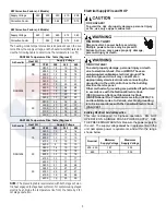
*Note: Consult with the condenser specific ations for suc tion and liquid
line sizing.
Adjustable Variable Pitch
Fixed Diameter
Copper Tubes / Al Fins
Thermal Expansion Valve (TXV)
Non-adjustable (factory installed)
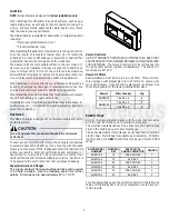
Unit Inspection
Upon delivery, the unit is to be inspected for damage. Any dam-
age must be reported immediately to the carrier. Do not install
this equipment if it is determined that the integrity or safety has
been compromised by freight damage.
Using the table “Model Identification” section check the equip-
ment model number to ensure the unit is appropriately sized for
the condenser unit(s).
If an incorrect unit is supplied it must not be installed and it is to
be returned to the supplier. The manufacturer assumes no re-
sponsibility for the installation of incorrect delivered units.
The evaporator coil contains a high-pressure inert gas holding
charge.
Codes & Regulations
This product is designed and manufactured to comply with na-
tional codes. Installation in accordance with such codes and/or
prevailing local codes/regulations is the responsibility of the in-
staller. The manufacturer assumes no responsibility for equip-
ment installed in violation of any codes or regulations.
The United States Environmental Protection Agency (EPA) has
issued various regulations regarding the introduction and dis-
posal of refrigerants. Failure to follow these regulations may
harm the environment and can lead to the imposition of sub-
stantial fines. Should you have any questions please contact the
local office of the EPA.
Replacement Parts
When reporting shortages or damages, or ordering repair parts,
give the complete product model and serial numbers as stamped
on the product. Replacement parts for this product are available
through your contractor or local distributor. For the location of
your nearest distributor consult the white business pages, the
yellow page section of the local telephone book or contact:
CONSUMER AFFAIRS
DAIKIN NORTH AMERICA LLC
7401 SECURITY WAY
HOUSTON, TEXAS 77040
855-770-5678
If replacing an air handler, the system must be manufacturer ap-
proved and Air-Conditioning, Heating, and Refrigeration Institute
(AHRI) matched. NOTE: Installation of unmatched systems is
strongly discouraged.
Pre-Installation Instructions
Carefully read all instructions for the installation prior to install-
ing product. Make sure each step or procedure is understood and
any special considerations are taken into account before starting
installation. Assemble all tools, hardware and supplies needed
to complete the installation. Some items may need to be pur-
chased locally. Make sure everything needed to install the prod-
uct is on hand before starting.