


10
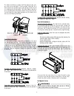
Evaporator Coil TXV
Note: Thermal Expansion Valve (TXV) Bulb is not permanently con-
nected to the suction from the factory. After suction and liquid
line tubing is brazed in the field, the TXV bulb must be attached
and insulation to the suction line(s) inside the cabinet at the 10 or
2 o’clock position. This location will be different depending on
the orientation of the unit, vertical or horizontal. Always locate
the TXV bulb on the top of the suction tube at 10 or 2 o’clock.
Check condensing unit / heat pump instructions for charging
method.
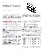
Airflow
The blower uses a belt drive motor that has an adjustable
sheave. The factory setting for the DAR0904 is 2 turns open
and the DAR1204 is 3 turns open.
To increase the airflow:
•
Remove the blower belt
•
Loosen the set screw as shown below
•
With the sheave stationary - rotate the other half clockwise
(screw in).
•
Tighten the set screw
•
Reinstall the belt
To decrease the airflow perform the same as above but rotate
the sheave counterclockwise (screw out).
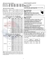
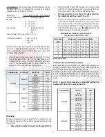
The following table can be used as guide for system airflow:
Static
Pressure
1
2
3
4
5
0.1
4264
3930
3633
3273
0.2
3996
3705
3325
2998
0.3
3731
3379
3002
2517
0.4
3445
3066
2613
-
0.5
3113
2662
-
-
DAR0904
Sheave Turns Open
Static
Pressure
0
1
2
3
4
5
0.1
5193
5037
4790
4529
4097
4097
0.2
5012
4873
4603
4315
3842
3842
0.3
4852
4675
4393
4091
3589
3589
0.4
4687
4484
4172
3853
3295
3073
0.5
4501
4268
3939
3561
2922
2610
0.6
4293
4041
3673
3223
2642
-
0.7
4073
3782
3347
2892
-
-
0.8
3807
3485
2962
-
-
-
0.9
3540
3117
-
-
-
-
DAR1204
Sheave Turns Open
Belt Tension
The belt tension is to be checked at the time of installation and
after a “run in” period of about 24 hours. To perform the
measurement, it is suggested that a “Belt Tension Gauge”
(available from most belt manufacturers) be used. The force
required to deflect the belt 1/8" (at the midpoint) should be
between 3 ½ and 5 pounds.


