


Control Devices
EDUS39-605
68
Controls
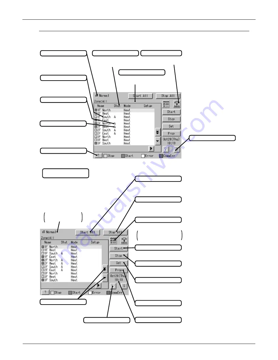
Lists:
Contents of the List Currently Displayed
y
When Group List is displayed
“Zone: Zone Name”
y
When Zone List is displayed
“Zone List”
Display Mode Selection
Press the button and display
change between Zone and Group.
System Condition Displayed Domain
Domain displaying system
condition (Compulsory Stop etc.)
Zone/Group Name
Set the names in the Group
Registration or Zone Registration
in the System Setup Mode.
Filter/Element Sign
Displayed when there is any air
conditioner showing a filter or
element sign in the zone or the
group.
Target of Automatic Control
Displayed when there is any air
conditioner with the registration of
scheduled in the zone or in the
group.
Monitoring Screen Legend
Pressing the “?” button shows
more detailed legend.
Button to Switch to the System Setup Mode
Use this button for settings
including the time, group, zone
and schedule.
Zone/Group Currently Displayed
The name of the zone/group
currently selected is highlighted
in light-blue.
Display for Collective Monitoring of Air
Conditioners Connected to intelligent Touch Controller
When operation is normal and any air
conditioner is in operation:
Red/Normal
When operation is normal and all air
conditioners are in stoppage:
Green/Normal
When there is any air conditioner
generating an error:
Yellow/Abnormal
When there is any air conditioner with
communication error:
Blue/Abnormal
Change in color of Start/Stop is
possible by Iconcolor Settings in
System Settings.
Start All Button
Button to collectively start all the
air conditioners connected to
intelligent Touch Controller.
Stop All Button
Button to collectively stop all the
air conditioners connected to
intelligent Touch Controller.
Display Mode Selection
Select the mode among
icon/list/detailed icon.
Displayed in List in the right figure.
Icon display is P467.
Detailed icon display is P468.
Group/Zone Start Button
Button to start operation of the
group/zone selected.
Group/Zone Stop Button
Button to stop operation of the
group/zone selected.
Group/Zone Set Button
Makes settings (temperature
setting, temperature control mode,
etc.) and display of the
group/zone selected.
Current Time Display
Shows the current date and time.
Group/Zone Prop Button
Detailed display of the
group/zone selected
Lock Setting/Cancel Button
Displays possibititiy of monitor
operation.
Scroll Buttons
Up/Down scroll button used when
monitoring zone/group which are
not currently displayed.
Left/Right scroll button used
when monitoring temperature
and errors etc.
Which are not currently
displayed.
75
˚F
75
˚F
75
˚F
75
˚F
75
˚F
75
˚F
77
˚F
75
˚F
75
˚F
75
˚F
75
˚F
75
˚F
75
˚F
75
˚F
75
˚F
75
˚F
75
˚F
77
˚F
75
˚F
75
˚F
75
˚F
75
˚F
Содержание BRC1C71
Страница 1: ......
Страница 8: ...EDUS39 605 Control Devices Controls 7 2 1 6 Installation ...
Страница 9: ...Control Devices EDUS39 605 8 Controls 18 2AWG ...
Страница 13: ...Control Devices EDUS39 605 12 Controls BRC7E83 BRC7E818 3D049336 C 3D034905B 2 7 16 11 16 6 3 16 ...
Страница 70: ...EDUS39 605 Control Devices Controls 69 2 8 7 Electrical Wiring Connection ...
Страница 71: ...Control Devices EDUS39 605 70 Controls ...
Страница 72: ...EDUS39 605 Control Devices Controls 71 ...
Страница 73: ...Control Devices EDUS39 605 72 Controls 1P167242A ...
Страница 77: ...Adaptors EDUS39 605 76 Controls C 1PA63164D 2 ...
Страница 78: ...EDUS39 605 Adaptors Controls 77 3 3 DTA109A51 DIII NET Expander Adaptor ...
Страница 79: ...Adaptors EDUS39 605 78 Controls ...
Страница 80: ...EDUS39 605 Adaptors Controls 79 ...
Страница 81: ...Adaptors EDUS39 605 80 Controls 3 4 KRP1B71 72 73 Adaptor for wiring ...
Страница 82: ...EDUS39 605 Adaptors Controls 81 C 2P164806 ...
Страница 83: ...Adaptors EDUS39 605 82 Controls 3 5 KRP4A71 72 73 74 Wiring Adaptor for Electrical Appendices ...
Страница 84: ...EDUS39 605 Adaptors Controls 83 1P161220 ...
Страница 85: ...Adaptors EDUS39 605 84 Controls ...
Страница 86: ...EDUS39 605 Adaptors Controls 85 ...
Страница 87: ...Adaptors EDUS39 605 86 Controls C 1P161221 ...


