


SFLC-211-185
55
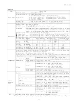
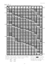
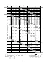
6. Specification
6.1 Specification and intrinsic error.
Input circuit
Input
3-phase 3-wire
Single-phase 2-wire
AC110V,220V common use. AC5A 50/60Hz
Single-phase 3-wire
AC100-200V (
26
), AC5A 50/60Hz
Note (
26
) The rated voltage of each phase and W phase is 100V. However, the full scale of a bar graph is 300V.
Measurement
item
Measurement range /
Display specification
Intrinsic error (
27
)
Maximum
measur-
ement
(
32
)
Minimum
measur-
ement
(
32
)
Notes
Digital
display
Analog output
(
28
)
Voltage
AC150V~750kV
±0.5%
±0.5%
○
○
RY-YB-BR line change (
29
)
Current
Maximum demand, Demand, Instant
AC5A~30kA
±0.5%
±0.5%
○
○
R-Y-B phase change (
30
)
Apart from a measurement
range, range setting of a
display and an output is
possible.
Active power
Maximum demand, Demand, Instant
150W~1200MW (Range select)
In voltage and current range.
One-way deflection or both
deflection can be setting.
±0.5%
±0.5%
○
○
Range of an analog output
can be set as indication
independently.
(
31
)
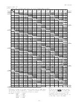
Reactive
power
LEAD,LAG 150var~1200Mvar
(Range select)
In voltage and current range.
±0.5%
±0.5%
○
○
Range of an analog output
can be set as indication
independently.
Power factor
LEAD 0.500~1.000~LAG 0.500 or
LEAD 0.000~1.000~LAG 0.000
Range select
±2.0%
±2.0%
○
○
In case input is below
20% of voltage range or
below 2% of current
range:cosφ=1. (Output
is cosφ=1 equivalence.)
Frequency
45~55Hz or
55~65Hz or
45~65Hz
Range select
±0.5%
±0.5%
○
○
0.0Hz in case input is
below 20% of voltage
range. Output is a
lower limit value.
(Lower limit value -1%
:% for output span)
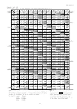
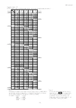
Measurement
item
Measurement range /
Display specification
Intrinsic error (
27
)
Maximum
measur-
ement
(
32
)
Minimum
measur-
ement
(
32
)
Notes
Digital
display
Pulse output
(
28
)
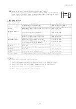
Watt-hour
Display:Integer, 5 digit.
Multiplier:Integral number time of 10.
Expansion display is possible to the
3rd place below a decimal point.
Electric power is integrated. (Power
receiving,Power transmission)
Power factor
1:±2.0%
Power factor
0.5:±2.5%
Power factor
1:±2.0%
Power factor
0.5:±2.5%
Conformity with normal
watt-hour meter.
Setting range of pulse
output unit (kWh/pulse)
is referred to
option-specification.
var-hour
Display:Integer, 5 digit.
Multiplier:Integral number time of 10.
Expansion display is possible to the
3rd place below a decimal point.
Integrating reactive power of power
receiving. (LAG・LEAD)
Integrating reactive power of power
transmission. (LAG・LEAD)
Power factor
0:±2.5%
Power factor
0.87
:±2.5%
Power factor
0:±2.5%
Power factor
0.87
:±2.5%
Setting range of pulse
output unit (kvarh/pulse)
is referred to option-
specification.
Note (
27
) If this unit directly measures an inverter output of cycle control, SCR phase angle control or PWM control,
an error may increase due to its operation principle.
Note (
28
) Analog output, pulse output, alarm output and external operation input are options.
Note (
29
) Single-phase 3-wire (R-B-W):RW-BW-RB, Single-phase 3-wire (R-Y-W):RW-YW-RY, Single-phase 3-wire (Y-B-W)
:YW-BW-YB, Single-phase 2-wire:With no phase display.
Note (
30
) Single-phase 3-wire (R-B-W):R-B-W, Single-phase 3-wire (R-Y-W):R-Y-W, Single-phase 3-wire (Y-B-W):
Y-B-W, Single-phase 2-wire:With no phase display.
Note (
31
) At the case of one-way deflection setting of bar graph. Digital meter measures reverse power to -15%
full scale.
Note (
32
) It can usually check the maximum value and the minimum value by MAX/MIN switch operation from a display.


