5
3 DVR Components
Check the label on the bottom of the DVR and note the model number and the power requirements
for this DVR. The label on the rear panel lists the serial number for the DVR. Please provide this serial
number when requesting information or service for this device.
3.1 Front Panel
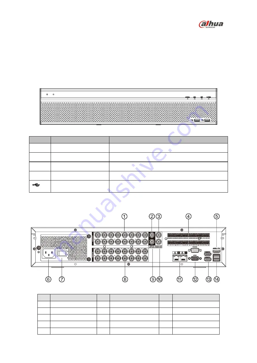
The figure below depicts the DVR front panel.
Figure 3-1
Light
Name
Function
STATUS Status indicator
Blue light indicates the device is working normally.
HDD
HDD status indicator
Blue light indicates the HDD is malfunctioning.
NET
Network status indicator
Blue light indicates the network connection is abnormal.
POWER
Power status indicator
Blue light indicates the power connection is OK.
USB 2.0 port (x2)
Connect to a peripheral USB 2.0 device (storage mouse,
CD/DVD burner).
3.2 Rear Panel
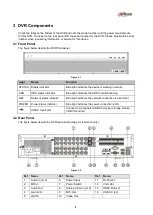
The figure below depicts the DVR rear panel (image for reference only).
Figure 3-2
Ref
Name
Ref
Name
Ref
Name
1
Audio In (x16)
6
Power Input
11
RJ45 (x2)
2
MIC In
7
Power Switch
12
VGA Out
3
Audio Out
8
Analog Video In (x16)
13
HDMI Out (x2)
4
Alarm I/O
9
MIC Out
14
USB 3.0 (x2)
5
eSATA
10
Video Out
Содержание X58A3S
Страница 8: ...6...


