


Local Configurations
206
5.15
Configuring Account Settings
You can add, modify and delete user accounts, groups, and ONVIF users, and set security
questions for admin account.
The user name supports 31 characters and group name supports 15 characters. The user
name can be consisted of letter, number, "_", "@", ".".
You can set maximum 64 users and 20 groups. The group name by "User" and "Admin"
cannot be deleted. You can set other groups and define the relevant permissions. However,
the admin account cannot be set randomly.
You can manage the account by user and group and the name cannot be repeated. Every
user must belong to a group, and one user only belongs to one group.
5.15.1
Configuring User Account
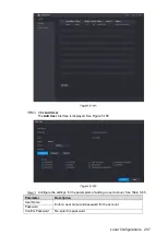
5.15.1.1
Adding a User Account
Select
Main Menu > ACCOUNT > USER
.
The
USER
interface is displayed. See Figure 5-184.
Содержание Smart 1U
Страница 1: ...DIGITAL VIDEO RECORDER User s Manual V1 0 0...
Страница 30: ...Connecting Basics 20...
Страница 80: ...Local Configurations 70 No Icon Description...
Страница 181: ...Local Configurations 171 Select the Enable check boxes to enable IoT function See Figure 5 152...
Страница 234: ...Local Configurations 224...
Страница 280: ...Glossary 270 Abbreviations Full term VGA Video Graphics Array WAN Wide Area Network...
Страница 298: ...Earthing 288...


