205
Call Scan
In Figure 4-86, input Scan value and then click
to call a tour. Click again
to stop call.
Rotate
In Figure 4-86, click
to enable the camera to rotate.
System supports preset, tour, pattern, scan, rotate, light and etc function.
Note:
Preset, tour and pattern all need the value to be the control parameters. You can define it as yo u
require.
You need to refer to your camera user’s manual for Aux definition. In some cases , it can be used for
special process.
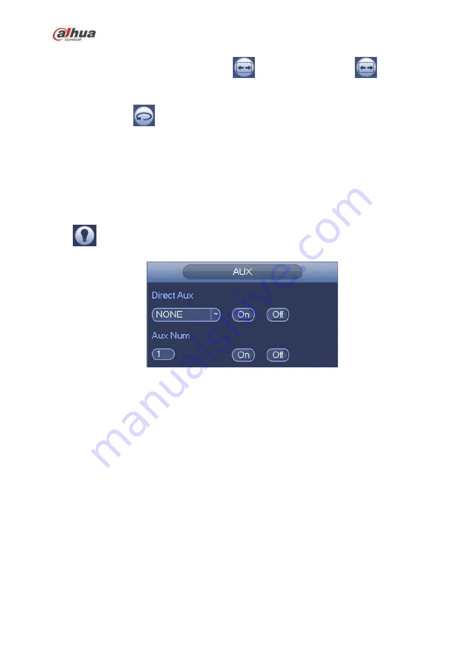
Aux
Click
, system goes to the following interface. The options here are defined by the protocol. The aux
number is corresponding to the aux on-off button of the decoder. See Figure 4-92.
Figure 4-92
4.5 Record File
Device adopts 24-hour continuous record by default. It supports customized record period and record
type. Refer to chapter 4.1.4.6 Schedule for detailed information.
4.6 Playback and Search
4.6.1
Instant Playback
Please refer to chapter 4.3.2 for real-time playback information.
4.6.2
Search Interface
From Main menu->Search, or on the preview interface right click mouse and then select search item, you
can go to the following interface. See Figure 4-93 or Figure 4-94.
Содержание NVR1A-4P Series
Страница 1: ...Dahua Network Video Recorder User s Manual V 4 3 0 ...
Страница 138: ...124 Figure 3 5 3 6 6 NVR42N Series Please refer to Figure 3 6 for connection sample Figure 3 6 ...
Страница 142: ...128 Figure 3 11 3 6 12 NVR42V 8P Series Please refer to Figure 3 12 for connection sample ...
Страница 143: ...129 Figure 3 12 ...
Страница 157: ...143 Figure 4 15 Step 2 Click device display edit interface See Figure 4 16 ...
Страница 220: ...206 Figure 4 93 Figure 4 94 ...
Страница 240: ...226 Figure 4 110 Figure 4 111 Figure 4 112 ...
Страница 251: ...237 Figure 4 123 Figure 4 124 ...
Страница 253: ...239 Figure 4 126 Click draw button to draw the zone See Figure 4 127 ...
Страница 257: ...243 Figure 4 130 Click Draw button to draw a zone See Figure 4 131 Figure 4 131 ...
Страница 262: ...248 Figure 4 136 Click draw button to draw the zone See Figure 4 137 ...
Страница 275: ...261 Figure 4 148 Figure 4 149 ...
Страница 276: ...262 Figure 4 150 Figure 4 151 ...
Страница 387: ...373 Figure 5 60 Figure 5 61 ...
Страница 388: ...374 Figure 5 62 Figure 5 63 ...
Страница 412: ...398 Figure 5 96 Figure 5 97 ...
Страница 418: ...404 Figure 5 106 5 10 4 4 Record Control The interface is shown as in Figure 5 107 Figure 5 107 ...


