

5
4
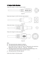
Installation
Attention:
Please install the device in time after it is taken apart, which is to avoid the camera
module being exposed to damp environment for too long.
Before the installation, please make sure the installation surface is thick enough to sustain
at least 3X weight of the camera.
Please don’t tear off the electrostatic adsorption film on the surface of transparent cover
before installation debugging is completed, which is to avoid damage during installation.
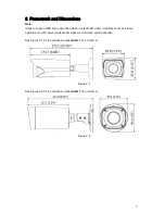
The installation figures below are for reference only, please refer to the actual model for
more details.
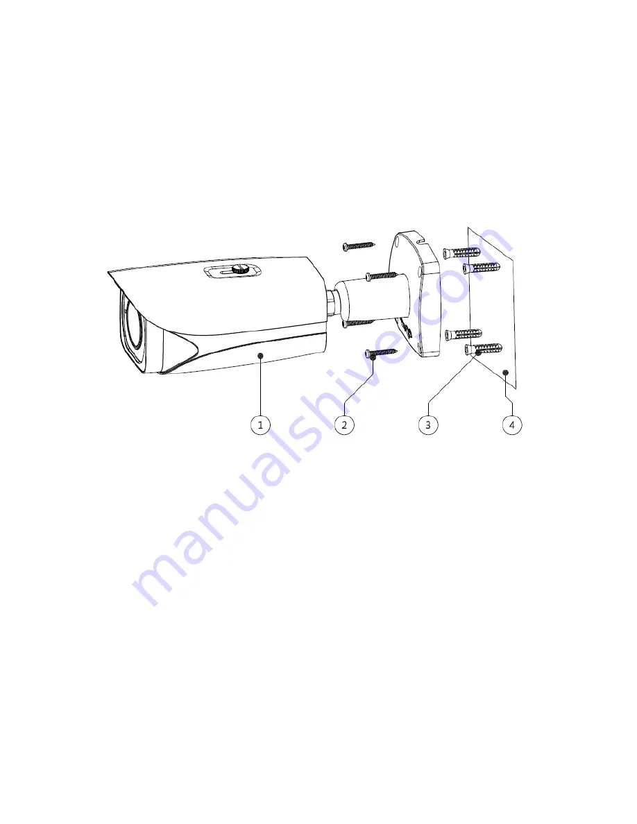
Figure 4-1
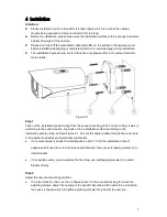
Step 1
Take out the installation position map from the accessories bag, stick it on the ceiling or wall
④
according to the outlet location, dig holes on the installation surface according to the
installation position map, and see Figure 4-1. Pull out the camera cable through the outlet hole
on the bracket pedestal, and install camera bracket.
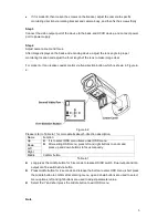
If it is cement wall, it needs to install expansion bolt
③
first (the installation holes of
expansion bolt need to be in accordance with bracket), then use self-tapping screws
②
to
install bracket.
If it is wooden wall, you can just skip the first step, use self-tapping screws
②
to install
bracket directly.
Step 2
Adjust the camera monitoring direction
If it is the model A, then use the L-shaped wrench in the accessories bag to loosen the
adjusting screws, adjust the camera to the specific direction which needs to be monitored,
then use L-shaped wrench to tighten adjusting screws firmly and fix the camera.
Содержание HAC-HFW2401R-Z-IRE6
Страница 1: ...HDCVI Camera User s Manual Version 1 0 0 ...