background image

Installation  and  Configuration     

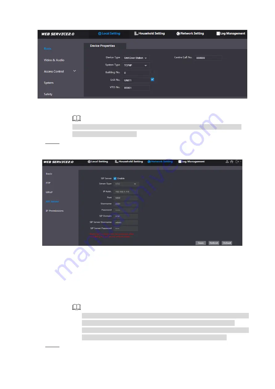
 Device properties 

Figure 2-6


1)  Select 

TCP/IP

 from the 

System Type

 drop-down list. 

2)  Click 

OK

 to save the settings. 


Restart the device manually, or wait for the device to restart automatically, and 

then the settings can be valid. 

  Log in to the web interface again, and then select 

Network Setting > SIP Server

Step 8

The 

SIP Server

 interface is displayed. See Figure 2-7. 

 SIP server (1) 

Figure 2-7


1)  Select server type. 

  When  this  VTO  or  another  VTO  works  as  SIP  server,  select 

VTO

  from  the


Server Type

 drop-down list. It applies to a scenario where there is only one 

unit. 

  When  the  platform  (

Express/DSS

)  works  as  SIP  server,  select


Express/DSS


from the

 Server Type

 drop-down list. It applies to a scenario where there are 

multiple buildings or multiple units. 

2)  Set VTO number and click 

OK

 to save the configuration. 


When the platform works as SIP server, if it is necessary to set Building No. 

and Building Unit No, enable 

Support Building

 and 

Support Unit

 first. 


After  VTO  is  set  to  be  SIP  server,  group  call  function  will  appear  on  the 

interface. To realize group call, select 

Enable

 next to the group call. 

  Select 

Network Setting > SIP Server

Step 9

The 

SIP Server

 interface is displayed. See Figure 2-8. 

Содержание Digital VTH Series

Страница 1: ...Digital VTH Version 4 2 Quick Start Guide V1 0 0...

Страница 2: ...ccording to the latest laws and regulations of related regions For detailed information see the paper manual CD ROM QR code or our official website If there is inconsistency between paper manual and t...

Страница 3: ...the device do not put on the device anything filled with liquids in order to prevent liquids from flowing into the device Install the device at well ventilated places do not block its vent Use the de...

Страница 4: ...2 Installation and Configuration 2 Installation 2 2 1 2 1 1 Surface Installation 2 2 1 2 Installation with 86 Box 2 2 1 3 Desktop Installation 3 Configuration 4 2 2 2 2 1 VTO Settings 4 2 2 2 VTH Set...

Страница 5: ...Rear Panel Port 1 1 Rear Panel Port VTH5421E H 1 1 Rear panel of VTH5421E H Figure 1 1 VTH5421CHM 1 2 Rear panel of VTH5421CHM Figure 1 2...

Страница 6: ...1 4cm 1 6cm above the ground 2 1 1 Surface Installation Directly install the device with a bracket onto a wall which is suitable for all types of devices Take VTH1550CH for example Drill holes in the...

Страница 7: ...andset VTH Take VTH5221E H as an example With two M3 6 cross recessed countersunk head screws tighten the metal bracket Step 1 onto the top two nuts of desktop bracket Connect cables For details see 1...

Страница 8: ...and VTH info on the web interface of every VTO set VTH info network info and VTO info on every VTH and thus realize video intercom function 2 2 1 VTO Settings VTO interfaces of different models might...

Страница 9: ...The TCP IP interface is displayed See Figure 2 5 TCP IP Figure 2 5 Enter the planned IP address subnet mask and gateway and then click OK Step 6 After modification VTO will restart automatically whil...

Страница 10: ...the Server Type drop down list It applies to a scenario where there is only one unit When the platform Express DSS works as SIP server select Express DSS from the Server Type drop down list It applies...

Страница 11: ...lt when the platform works as SIP server Username Password Use default value SIP Domain It shall be VDP when another VTO works as SIP server It can be null or keep default value when the platform work...

Страница 12: ...e unit where VTO is located IP Address IP address of VTO Username Password Username and password to log in to the web interface of this VTO Optional Select Household Setting Room No Management Step 12...

Страница 13: ...itialization For first time use initialize the password and bind email Password is used to enter project setting interface while email is used to retrieve your password when you forget it Power on the...

Страница 14: ...LAN Enter local IP subnet mask and gateway and then tap OK Or tap to enable DHCP function and obtain IP info automatically If the device has WLAN function tap WLAN to set it WLAN 1 Tap to enable Wi F...

Страница 15: ...local IP subnet mask and gateway and then tap OK At WLAN interface select Wi Fi tap Wireless IP tap to enable DHCP function and obtain IP info automatically To obtain IP info with DHCP function use a...

Страница 16: ...assword of master VTH Default user name is admin and the password is the one set during device initialization Security module is On by default keep the default status 3 Tap OK to save settings Tap SIP...

Страница 17: ...TO Config interface is displayed see Figure 2 17 VTO configuration Figure 2 17 Add VTO or fence station Step 8 Add main VTO 1 Enter main VTO name VTO IP address user name and password 2 Switch the Ena...

Страница 18: ...y Call VTH from VTO Figure 2 18 2 3 2 VTH Monitors VTO VTH is able to monitor VTO fence station or IPC Take VTO for example Select Monitor Door see Figure 2 19 Select the VTO to enter monitoring image...

Страница 19: ...Installation and Configuration 15 Door Figure 2 19 Monitoring image Figure 2 20...

Страница 20: ...ed to enable the auto check for updates function to obtain timely information of firmware updates released by the manufacturer We suggest that you download and use the latest version of client softwar...

Страница 21: ...llowing services SNMP Choose SNMP v3 and set up strong encryption passwords and authentication passwords SMTP Choose TLS to access mailbox server FTP Choose SFTP and set up strong passwords AP hotspot...

Страница 22: ...s If there are no communication requirements between two sub networks it is suggested to use VLAN network GAP and other technologies to partition the network so as to achieve the network isolation eff...

Отзывы: