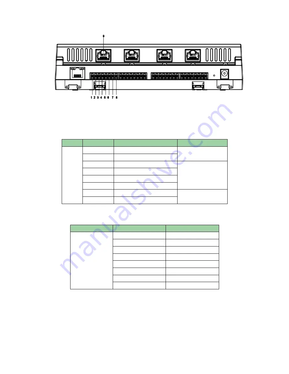
9
Figure 4- 3
Cabling ports of “No. 1 entry card reader” are as follows. It is same for “No.1 door’s card
reader”, “No.2 door’s card reader”, “No.3 door’s card reader” and “No.4 door’s card reader”.
Port
No.
Cabling Port
Note
No.1
Entry
Card
Reader
1
485+
485 card reader
2
485-
3
LED
Wiegand card reader
4
D0
5
D1
6
CASE
7
GND
Card reader power
8
12V
4 RJ45 cables’ colors are defined as follows:
No.
Cabling Port
Color
9
485+
White-orange
485-
Orange
LED
White-green
D0
Blue
D1
White-blue
CASE
Green
GND
White-brown
12V
Brown
4.3 System Structure
The access controller, lock, card reader and etc. combine a system as in Figure 4- 4.
Содержание ASC1204B-S
Страница 1: ...1 Four Door Access Controller User s Manual V1 0 2...
Страница 14: ...10 Figure 4 4...


