background image

Interface Configuration

21

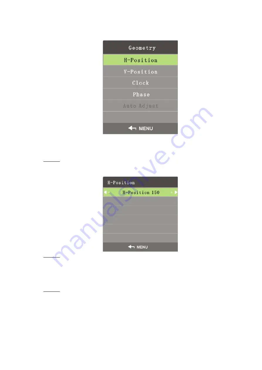
On the main menu, press the left and right direction buttons until the

Geometry

interface is

displayed. See Figure 4-11.

Figure 4-11 Geometry (VGA)

H-Position

H-Position is used to adjust the horizontal position of the video wall.
Step 1 On the

Geometry

menu, select

H-Position

.

The

H-Position

interface is displayed. See Figure 4-12.

Figure 4-12 H-position

Step 2 Adjust the horizontal position by the left and right buttons on the remote control

according to your requirement.

V-Position

You can adjust the vertical position of the video wall by adjusting v-position.
Step 1 On the

Geometry

menu, select

V-Position

.

The

V-Position

interface is displayed. See Figure 4-13.

Содержание DHI-LS550UCM-EF

Страница 1: ...1 LSxxxUCM EF_LCD Video Wall User s Manual V1 0 1...

Страница 2: ...be changed to any set of numbers between 1025 65535 Avoiding the default ports reduces the risk of outsiders being able to guess which ports you are using 3 Enable HTTPS SSL Set up an SSL Certificate...

Страница 3: ...SNMP you should do so only temporarily for tracing and testing purposes only 12 Multicast Multicast is used to share video streams between two recorders Currently there are no known issues involving...

Страница 4: ...he guide may cause harmful interference to radio communication For class A device these limits are designed to provide reasonable protection against harmful interference in a commercial environment Op...

Страница 5: ...s lower performance or unpredictable result TIPS Provides methods to help you solve a problem or save you time NOTE Provides additional information as the emphasis and supplement to the text Revision...

Страница 6: ...otice The product updates might cause some differences between the actual product and the Manual Please contact the customer service for the latest program and supplementary documentation There still...

Страница 7: ...5 4 1 Picture 16 4 1 1 Image Mode 16 4 1 2 Contrast 17 4 1 3 Brightness 17 4 1 4 Saturability 18 4 1 5 Sharpness 18 4 1 6 Color Temperature 19 4 1 7 Aspect Ratio 19 4 1 8 Noise Reduction 20 4 2 Geomet...

Страница 8: ...emperature of the video wall will increase and fire might occur 1 2 Maintenance Tips Comply with the maintenance rule strictly to prolong the life span of the video wall and to implement energy conser...

Страница 9: ...rs in the server room and the room where the video wall is installed are the same If the video wall has been off for a long time check if there are water drops on the surface If there are water drops...

Страница 10: ...o do the maintenance If the video wall is not in use for a long time it will gather dust and heat radiation will be influenced Dust Proof Requirement During debugging and operation the dust concentrat...

Страница 11: ...nts are complete The actual appearance items or quantity might be different depending on the mode you purchased and the actual packing list shall prevail Table 2 1 Packing list Component Quantity Liqu...

Страница 12: ...igure 3 2 Port Table 3 1 Port description No Port Function 1 Power output port Outputs AC current 2 Power input port Inputs AC current 3 Power switch Controls the on and off of the AC input port 4 LAN...

Страница 13: ...ntrol is a must have device For functions of its buttons see Table 3 2 Table 3 2 Button functions Picture No Name Function 1 Power Power on Standby 2 Address Shortcut keyboard for address setting dedi...

Страница 14: ...f you have selected voice you can use these buttons to adjust the volume Up and down direction button Use it to select items up or below the current item you have selected on the screen 9 Image mode S...

Страница 15: ...the video wall Geometric icon used to set positions for images Sound icon used to adjust volume for the videos played on the video wall Advanced icon used to do advanced settings to images Advanced op...

Страница 16: ...re 4 1 1 Image Mode You can adjust the overall effects of images through image mode Step 1 Press Menu on the remote control The Image Mode interface is displayed See Figure 4 3 Figure 4 3 Image Mode S...

Страница 17: ...displayed See Figure 4 4 Figure 4 4 Contrast Step 2 Adjust the Contrast by the left and right buttons on the remote control according to your requirement The range of contrast is 0 100 4 1 3 Brightnes...

Страница 18: ...on the remote control according to your requirement The range of saturability is 0 100 4 1 5 Sharpness Definition of images can be adjusted by adjusting sharpness The higher the sharpness is the clea...

Страница 19: ...andard warm and personal Only in user mode can you adjust the value of red green and blue 4 1 7 Aspect Ratio Display scales can be adjusted by adjusting aspect ratio Step 1 Select Image Aspect Ratio T...

Страница 20: ...trol to complete the setting 4 1 8 Noise Reduction To improve quality of images adjust the noise reduction Only in CVBS signal mode can you select image noise deduction function Step 1 Select Image No...

Страница 21: ...ideo wall Step 1 On the Geometry menu select H Position The H Position interface is displayed See Figure 4 12 Figure 4 12 H position Step 2 Adjust the horizontal position by the left and right buttons...

Страница 22: ...e higher the frequency more accurate the signals are Step 1 On the Geometry menu select Sampling Frequency The Sampling Frequency interface is displayed See Figure 4 14 Figure 4 14 Sampling frequency...

Страница 23: ...ct Auto Adjust The Auto Adjust interface is displayed See Figure 4 16 Figure 4 16 Auto adjust Step 2 Press Menu on the remote control and then the position of the screen will be automatically adjusted...

Страница 24: ...e 4 18 Figure 4 18 Sound adjust Step 3 Adjust the on and off status of the sound adjust by the left and right buttons on the remote control If you select off then the video wall is in silent mode 4 4...

Страница 25: ...n the Advanced menu You can select Advanced by the up and down buttons on the remote control See Figure 4 20 Figure 4 20 Enter passwords The default password is 8888 On the Advanced interface technica...

Страница 26: ...software update files must be stored at the first level directory otherwise the files cannot be identified 4 4 4 Mirror Image Press the up and down direction buttons on the remote control to select Mi...

Страница 27: ...layed See Figure 4 23 Figure 4 23 OSD language Step 2 Select the OSD language by the left and right buttons OSD language includes English and Chinese Step 3 Press Menu on the remote control to complet...

Страница 28: ...3 OSD Blending OSD blending is used to set the transparency for the menu Step 1 Select System OSD Blending The OSD Blending interface is displayed See Figure 4 25 Figure 4 25 OSD Blending Step 2 Adjus...

Страница 29: ...ddress Switch The Soft Address Switch interface is displayed See Figure 4 27 Figure 4 27 Soft address switch Step 2 Set soft address by the left and right buttons on the remote control according to yo...

Страница 30: ...ry settings by the left and right buttons on the remote control according to your requirement Step 3 Press Menu on the remote control to complete the setting 4 6 Input Source You can select input sign...

Страница 31: ...a 1 2 Select photo music movie and text by the left and right buttons on the remote control and then press Enter the interface of items you selected is displayed See Figure 4 31 Figure 4 31 Multimedia...

Страница 32: ...ether the indicator light is on Blank screen no signal displayed Check whether the signal wires are in bad contact Check whether there is signal source output Check whether the signal wires are broken...

Отзывы: