background image


3.3  Alarm Setup 

Certain devices support alarm inputs and outputs, check your specific device for alarm capability.  

Alarm Input 

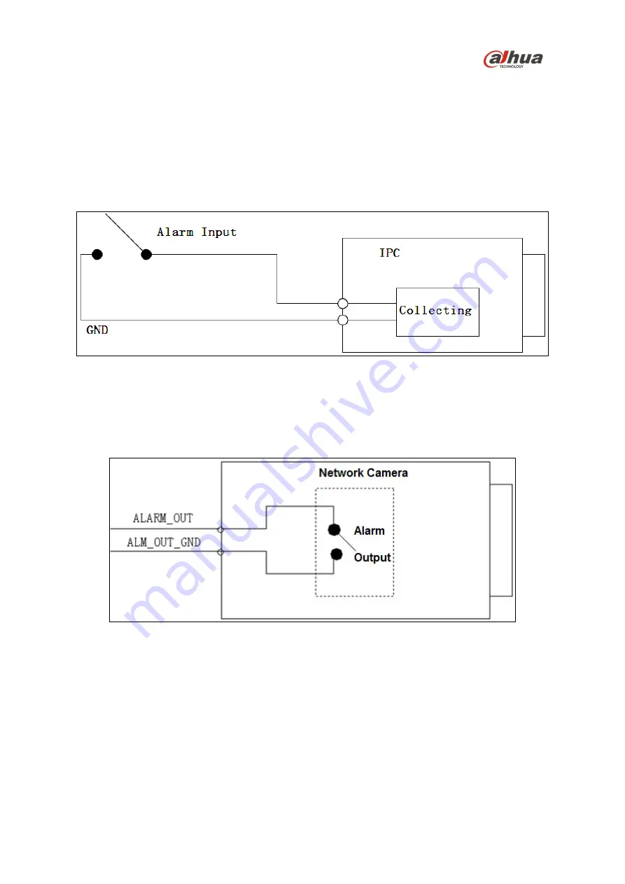
Refer to Figure 3-3 for alarm input configuration. The device collects that status of the alarm input port 

when the input signal is idle or grounded. If the input signal is connected to the 3.3V or it is idle then 

the device receives the alarm input signal. If input signal is grounded, then no alarm input signal is 

detected. 


Figure 3-3 

Alarm Output 

The ALARM_OUT and the ALM_OUT_GND ports form a switch, which is used to provide alarm 

output. Normally the switch is on when there is no output signal. The switch is turned off when an 

alarm output signal is present.  


Figure 3-4 

1.  Connect the alarm input device to the ALARM_IN1 or ALARM_IN2 connector on the I/O port 

cable. 

2.  Connect an alarm output device to the ALARM_OUT and to the ALARM_OUT_GND connectors 

on the I/O port cable. The Alarm Output can only be connected to a Normally Open (NO) alarm 

device.  

Содержание DH-IPC-PFW8601N-H-A180

Страница 1: ...Multi Sensor Panoramic IR Bullet Camera Quick Start Guide Version 1 0 1 Dahua Technology USA Inc ...

Страница 2: ...t 4 Trademarks 4 1 4 Disclaimer 4 2 Unpacking 5 3 Installation and Configuration 6 3 1 External Cable 6 Cable Connections 6 Alarm I O Port Configuration 7 3 2 Framework and Dimensions 7 3 3 Alarm Setup 8 Alarm Input 8 Alarm Output 8 4 Device Installation 9 4 1 Installing the Camera 9 5 Network Configuration 12 5 1 Modifying the IP Address 12 5 2 Using the ConfigTool 12 5 3 Accessing the Web Interf...

Страница 3: ...o protect the unit from damage especially in damp environments Protect the plug and power cord from foot traffic being pinched and its exit from the unit Units with or without an ON OFF switch have power supplied to the unit whenever the power cord is inserted into the power source however the unit is operational only when the ON OFF switch is in the ON position The power cord is the main power di...

Страница 4: ...ing or installation Environmental Precautions Do not aim the unit at a strong light source or into direct sunlight to focus A strong light source may cause overexposure and may affect the longevity of the CCD or the CMOS sensor Transport use and store the unit within the specified temperature and humidity range Do not place the unit in a wet dusty extremely hot or an extremely cold environment and...

Страница 5: ...le solvent like alcohol benzene or thinner or use a strong detergent with abrasives which may damage the surface coating or reduce the working performance of the unit Do not touch or wipe a dome cover during installation this cover is an optical device Refer to the following methods clean the dome cover Stained with dirt Use an oil free soft brush or blower to gently remove the dirt Stained with g...

Страница 6: ...r guide is 2016 Dahua Technology Company LTD This user guide is the intellectual property of Dahua Technology Company LTD and is protected by copyright All rights reserved Trademarks All hardware and software product names used in this document are likely to be registered trademarks and must be treated accordingly 1 4 Disclaimer This user guide has been compiled with great care and the information...

Страница 7: ...fest container to transport the unit in the event the unit must be returned for service Retain the carton and all shipping material for future use Please refer to the enclosed CD for more details to view the detailed User s Manual and for configuration software Package Item Quantity Multi Sensor Bullet Camera 1 Mounting Template 1 Multi Purpose Tool 1 Installation Hardware Pack 1 Expansion Bolts 4...

Страница 8: ...ceive an analog audio signal from an external pickup 3 LAN Network port Ethernet port Connect to standard Ethernet cable Note Certain devices support Power over Ethernet Check the specific device to determine if the device accepts PoE and use an appropriate Ethernet cable and network to supply power 4 I O I O port Alarm signal input output Refer to Table 3 2 for more details 5 Power Power input po...

Страница 9: ... Alarm input port 1 Use to receive the On Off signal from an external alarm source 4 ALARM_IN2 Alarm input port 2 Use to receive the On Off signal from an external alarm source 5 ALARM_IN_GND Alarm input ground port Table 3 2 3 2 Framework and Dimensions The following figures show the dimensions of the device in mm These images are intended as a reference only Figure 3 2 ...

Страница 10: ...nput signal is grounded then no alarm input signal is detected Figure 3 3 Alarm Output The ALARM_OUT and the ALM_OUT_GND ports form a switch which is used to provide alarm output Normally the switch is on when there is no output signal The switch is turned off when an alarm output signal is present Figure 3 4 1 Connect the alarm input device to the ALARM_IN1 or ALARM_IN2 connector on the I O port ...

Страница 11: ...nd a bracket if used DO NOT connect the camera to the power supply during installation Figure 4 1 4 1 Installing the Camera 1 Remove the camera the mounting template multi purpose tool and the hardware package from the box 2 If you are using an SD card turn the camera to access the bottom of the camera 3 Insert an SD card into the SD Card Slot Refer to Figure 4 2 for the location of the SD Card sl...

Страница 12: ...of pliers and use the Multi purpose Tool to tighten the expansion bolt onto the nut Repeat this procedure with the other three 3 expansion bolts 13 Adjust the sunshield if necessary Loosen the screw on the top of the camera and slide the sunshield back and forth to the desired location then tighten the screw 14 Connect the external cables from the camera to the appropriate cables for Ethernet powe...

Страница 13: ...ulti purpose Tool to loosen the three set screws along the shaft of the camera then position the camera by tilting twisting and rotating the camera as shown in Figure 4 4 below Note Do not rotate the camera more than three 3 times in any one direction Figure 4 4 ...

Страница 14: ...plies the ConfigTool to access and to modify the network settings of a device Refer to the Operation Manual available on the CD included with the camera or on Dahuasecurity com for complete information Notes Ensure that the network parameters of each camera is available before starting configuration The ConfigTool supports those cameras that are part of the same network that as the computer runnin...

Страница 15: ...y have different Web interfaces the figures below are for reference only and may not represent the Web Interface for your camera Refer to the Web Operation Manual included on the CD shipped with the camera for more details 1 Launch Internet Explorer and type the modified camera IP address in the address bar Internet Explorer opens the Login page 2 Type the Username and Password for the camera The ...

Страница 16: ... page 2 Set the parameters for the alarm inputs Check the Enable box to activate the chosen alarm input Alarm 1 or Alarm 2 Set the sensor type for the alarm either Normally Open NO or Normally Closed NC 3 Check the Relay Out box to enable the alarm activation function 4 Select an alarm output port to activate a corresponding alarm device when an alarm occurs Check Send Email to have the device sen...

Страница 17: ...15 Dahua Technology USA Inc 23 Hubble Irvine CA 92618 Tel 949 679 7777 Fax 949 679 5760 Email sales usa global dahuatech com ...

Отзывы: