background image

TBM

PILOT’S OPERATING HANDBOOK

700

SECTION 7

DESCRIPTION

Page 7.12.2

Edition 1 -- November 30, 2010

Rev. 0

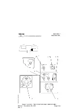
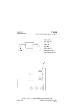
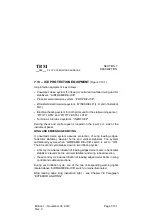
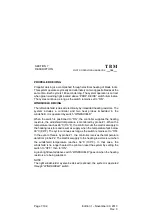
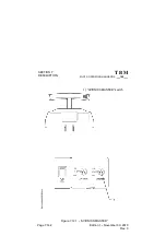
Figure 7.12.1 (1/2) -- VACUUM SYSTEM

1) Pressure regulator
2) Ejector
3) Valve
4) Regulating and relief valve
5) Pressure switch
6) Failure CAS message

Содержание TBM 700 A

Страница 1: ...PILOT S INFORMATION MANUAL TBM 700 Edition 1 ...

Страница 2: ... It must not be used for any purpose other than that for which it is supplied nor may information contained in it be disclosed to unauthorized persons It must not be reproduced nor transmitted in any form in whole or in part without permission in writing from the owners of the Copyright Information in this document is subject to change without notice 2010 SOCATA All rights reserved SOCATA DIRECTIO...

Страница 3: ...eel replacement Major 010 24 Increase of the inboard generators ratings minor 011 56 Installation of a bonding plate on de iced windshield minor 012 30 Pitch control horn de icing Major 013 34 VOR LOC Glide antenna system DORNE MARGOLIN DMN4 17N Major 015 24 ECE electric power center technical evolution Bus 4 minor 016 57 Addition of compensating edge on R H aileron minor 017 52 Improvement of pas...

Страница 4: ...e reinforcement Major 037 21 Cabin air conditioning Ground ventilation improvement minor 038 28 Fuel unit INTERTECHNIQUE L88A15 651 minor 039 27 Installation of pitch trim position transmitter minor 041 71 Reinforcement of NACA air intakes on cabin air conditioning system and engine oil cooling system minor 042 25 Cabin covering improvement lower door minor 043 32 Increasing in landing gear circui...

Страница 5: ...IN LHC 1118 04 minor 061 27 Elevator trim jack minor 062 24 Strengthening of AUXILEC starter generator mounting flange Major 063 32 Main gear tires minor 065 32 Removal of the main landing gear inboard doors Major 066 57 Wing attachment shafts minor 067 57 Simplification of the main landing gear fairings standard configuration minor 068 32 Nose gear tires minor 069 55 Corrosion on rudder and eleva...

Страница 6: ...91 52 TBM700B Access door widening incorporation of modifications and increase of maximum zero fuel weight Major 095 71 Engine plenum chamber minor 096 30 Modification of R H wing de icing hose routing and modification of the stall warning indicator attachment screw length minor 097 56 Windshield and side windows dry installation minor 099 35 Modification of the chemical oxygen cylinder opening pi...

Страница 7: ...17 55 Horizontal stabilizer reinforcement Major 119 71 Change of location of the oil pump breather outlet Major 120 55 Horizontal stabilizer outboard hinge fittings Major 121 76 Thermal protection of JACOTTET propeller control lever Major 122 57 Flap carriages Major 123 52 Stairs damping minor 124 71 Engine drains minor 126 53 Fuselage structure reinforcement Aircraft service life changed minor 12...

Страница 8: ...TERTECHNIQUE minor 0161 27 Aileron control emergency stop minor 0163 77 Torque transducer static port tube minor 0166 53 Change of glass fiber fabric type on TBM 700 composite floors minor 0168 57 Modification of TBM 700 internal flap carriage pin definition external flap carriages are processed by amendment minor 0172 57 Replacement on flaps of SHUR LOCK nuts by machined bushings minor 0173 28 Ne...

Страница 9: ...acement of fin expansion pins minor 0209 57 Reinforcement of trailing edge omega at rib 7 minor 0213 27 Pitch trim union connector at rear pressure bulkhead minor 0216 52 TBM 700A door upper mechanism Airplanes S N 1 to 9 11 to 17 19 to 22 25 to 27 29 to 35 38 46 49 not equipped as a retrofit with modification No MOD70 019 25 and equipped with an interior handle unlocking device through push butto...

Страница 10: ...0 Page 0 6 Edition 1 November 30 2010 Rev 0 TABLE OF CONTENTS SECTION GENERAL 1 LIMITATIONS 2 EMERGENCY PROCEDURES 3 NORMAL PROCEDURES 4 PERFORMANCE 5 WEIGHT AND BALANCE 6 DESCRIPTION 7 AIRPLANE HANDLING SERVICING AND MAINTENANCE 8 SUPPLEMENTS 9 ...

Страница 11: ...IN AND ENTRY DIMENSIONS 1 3 4 BAGGAGE SPACE ENTRY DIMENSIONS NON PRESSURIZED 1 3 4 SPECIFIC LOADINGS 1 3 4 1 4 ABBREVIATIONS AND TERMINOLOGY 1 4 1 METEOROLOGICAL TERMINOLOGY 1 4 1 GENERAL AIRSPEED TERMINOLOGY AND SYMBOLS 1 4 1 POWER TERMINOLOGY 1 4 3 AIRPLANE PERFORMANCE AND FLIGHT PLANNING TERMINOLOGY 1 4 4 WEIGHT AND BALANCE TERMINOLOGY 1 4 4 GENERAL ABBREVIATIONS 1 4 6 RADIO NAVIGATION ABBREVIA...

Страница 12: ...al data supplied by the manufacturer The GARMIN G1000 Integrated Flight Deck Cockpit Reference Guide for SOCATA TBM 700 P N 190 01247 00 or any later version as applicable must be permanently kept in the airplane with the Pilot s Operating Handbook Section 1 provides basic data and information of general interest It also contains definitions or explanations of abbreviations and terminology commonl...

Страница 13: ...ENERAL TBM 700 PILOT S OPERATING HANDBOOK Page 1 2 1 Edition 1 November 30 2010 Rev 0 1 2 THREE VIEW DRAWING Figure 1 2 1 1 2 THREE VIEW DRAWING TBM700A Airplane on line of flight with extended FWD shock absorber ...

Страница 14: ...TBM PILOT S OPERATING HANDBOOK 700 SECTION 1 GENERAL Page 1 2 2 Edition 1 November 30 2010 Rev 0 Figure 1 2 1 2 2 THREE VIEW DRAWING TBM700A ...

Страница 15: ...SECTION 1 GENERAL TBM 700 PILOT S OPERATING HANDBOOK Page 1 2 3 Edition 1 November 30 2010 Rev 0 Figure 1 2 1A 1 2 THREE VIEW DRAWING TBM700B Airplane on line of flight with extended FWD shock absorber ...

Страница 16: ...TBM PILOT S OPERATING HANDBOOK 700 SECTION 1 GENERAL Page 1 2 4 Edition 1 November 30 2010 Rev 0 Figure 1 2 1A 2 2 THREE VIEW DRAWING TBM700B ...

Страница 17: ...ype Annular Turbine type 1 gas generator turbine stage 2 power turbines stages Horsepower rating and propeller speed 700 SHP at 2000 RPM PROPELLER Number of propellers 1 Propeller manufacturer HARTZELL Propeller model number HC E4N 3 E9083S K Number of blades 4 Propeller diameter Minimum 90 inches 2 286 m Maximum 91 inches 2 311 m Propeller type Adjustable constant speed with feathering and hydrau...

Страница 18: ...ICTED TO EMERGENCY PURPOSES ONLY AVGAS SHALL NOT BE USED FOR MORE THAN 150 CUMULATIVE HOURS DURING ANY PERIOD BETWEEN ENGINE OVERHAUL PERIODS NOTE Use of AVGAS to be recorded in engine module logbook US Specification US French Specification FR English Specification UK NATO Code ASTM D1655 JET A ASTM D1655 JET A1 ASTM D1655 JET B AIR 3405C Grade F35 DERD 2494 Issue 9 F35 without additive MIL DTL 56...

Страница 19: ...ation FR English Specification UK NATO Code Type 5cSt MIL L 23699C Amdt1 MIL L 23699C Amdt1 DERD 2499 Issue 1 O 156 Figure 1 3 2 RECOMMENDED ENGINE OIL TYPES Reference Service Bulletin P W C No 14001 MAXIMUM CERTIFICATED WEIGHTS Ramp 6614 lbs 3000 kg Takeoff 6579 lbs 2984 kg Landing 6250 lbs 2835 kg Baggage weight refer to Section 6 for cargo loading instructions In FWD compartment non pressurized...

Страница 20: ... cabin length 13 3 45 4 05 m Maximum cabin height 4 1 22 m TBM700A Number of cabin entries 1 Entry width 2 1 59 0 65 m Entry height 3 10 85 1 19 m TBM700B Number of cabin entries 1 Entry width 3 6 52 1 08 m Entry height 3 10 85 1 19 m BAGGAGE SPACE ENTRY DIMENSIONS NON PRESSURIZED Access by L H side door Entry width 1 2 57 0 37 m Entry height 1 8 08 0 51 m SPECIFIC LOADINGS Wing loading 34 lbs sq ...

Страница 21: ...de if it is set to QNH Standard Temperature Is 15 C 59 F at sea level pressure altitude and decreases by 2 C 3 6 F for each 1000 ft of altitude Pressure altitude Is the altitude read from an altimeter when the altimeter s barometric scale has been set to 29 92 inches of mercury 1013 2 hPa GENERAL AIRSPEED TERMINOLOGY AND SYMBOLS KCAS Knots Calibrated Airspeed is the indicated airspeed expressed in...

Страница 22: ...e safely extended or retracted VMO Maximum Operating Speed is the speed limit that may not be deliberately exceeded in normal flight operations VR Rotation Speed is the speed at which rotation is initiated during takeoff to achieve takeoff safety speed at screen height VSO Stalling Speed or the minimum steady flight speed at which the airplane is controllable in the landing configuration VS1 Stall...

Страница 23: ...lue permissible during start Flame out Involuntary loss of the combustion chamber flame during operation GPU Ground power unit Feathering Action which reduces the drag of a propeller by positioning blades at the pitch angle allowing minimal drag Maximum Cruise Power Power developed corresponding to outside Flight Level and Temperature conditions Refer to Chapter 5 PERFORMANCE Ng Gas generator RPM ...

Страница 24: ...ted during certification tests The value shown is not considered to be limiting g Is acceleration due to gravity Usable fuel Total fuel which can be effectively consumed by the engine WEIGHT AND BALANCE TERMINOLOGY Reference datum Datum perpendicular to the longitudinal airplane centerline from which all distances are measured for balance purpose Arm Is the distance from the reference datum to the...

Страница 25: ...nusable fuel and full operating fluids oil and hydraulic fluids Basic empty weight Standard empty weight plus optional equipment Useful load Is the difference between maximum ramp weight and the basic empty weight Maximum ramp weight Is the maximum weight approved for ground maneuver It includes the weight of start taxi and run up fuel Maximum takeoff weight Is the maximum weight approved at the b...

Страница 26: ...y BRT Brightness CAS Crew Alerting System C Celsius degree CHiPS Cable Harness Protection System CONT Control DIEGME Diethylene glycol monomethyl ether DISC Disconnect DN Down ECS Environmental control system EGME Ethylene glycol monomethyl ether EMER Emergency ENCOD ALTI Encoding altimeter ESHP Estimated shaft horsepower ESS BUS TIE Essential BUS tie EXT LIGHTS Exterior lightings F Fahrenheit deg...

Страница 27: ...t l Litre L Left l h Litre hour lb or lbs Pound s L D Lift to drag LDG Landing LDG GR Landing gear LRCR Long Range Cruise LO Low LP Low pressure LRN Long range navigation LTS TEST Lightings test m Metre m a c Mean aerodynamic chord MAIN GEN Main generation MAN Manual MAN OVRD Manual override MAX RPM Maximum revolutions per minute MFD Multi function Display MIN Minimum min Minute MLW Maximum Landin...

Страница 28: ...rizontal stabilizer PRESS Pressure PROP Propeller psi Pounds per square inch qt Quart us gal QTY Quantity R Red or Right RUD Rudder s or sec Second SEL Selector SIG Signalization SL Sea level S N Serial number SPKR Speaker ST BY Stand by STALL HTR Stall heater Std Standard T Temperature TEMP Temperature TO Takeoff TURN COORD Turn coordinator us gal Gallon U S V Volt WARN Warning W S Windshield ...

Страница 29: ...ications Transceivers DME Distance Measuring Equipment ELT Emergency Locator Transmitter FMS Flight Management System GPS Ground Positioning System HF High Frequency IFR Instrument Flight Rules ILS Instrument Landing System IMC Instrument Meteorological Conditions L NAV Lateral NAVigation LPV Localizer Precision Vertical MKR Marker Radio Beacon NAV Navigation Indicators or Receivers P RNAV Precisi...

Страница 30: ...on 1 November 30 2010 Rev 0 VHF Very High Frequency VMC Visual Meteorological Conditions V NAV Vertical NAVigation VOR VHF Omnidirectional Range VOR LOC VHF Omnidirectional Range LOCalizer WAAS Wide Area Augmentation System WXR Weather surveillance radar XPDR Transponder ...

Страница 31: ...D U S UNITS TO METRIC UNITS METRIC UNITS TO IMPERIAL AND U S UNITS MULTIPLY BY TO OBTAIN MULTIPLY BY TO OBTAIN FEET 0 3048 METRE METRE 3 2808 FEET INCH 25 4 mm mm 0 03937 INCH Imp Gal 4 546 Litre Litre 0 220 Imp Gal us gal 3 785 Litre Litre 0 264 us gal lb 0 45359 kg kg 2 2046 lb Figure 1 5 1 IMPERIAL AND U S UNITS TO METRIC UNITS ...

Страница 32: ...TBM PILOT S OPERATING HANDBOOK 700 SECTION 1 GENERAL Page 1 5 2 Edition 1 November 30 2010 Rev 0 Figure 1 5 2 FEET VERSUS METRES Mètres 30000 20000 10000 0 Feet 2500 5000 7500 10000 ...

Страница 33: ...SECTION 1 GENERAL TBM 700 PILOT S OPERATING HANDBOOK Page 1 5 3 Edition 1 November 30 2010 Rev 0 Figure 1 5 3 INCHES VERSUS MILLIMETRES mm 10 0 In 250 500 750 1000 20 30 40 ...

Страница 34: ...TBM PILOT S OPERATING HANDBOOK 700 SECTION 1 GENERAL Page 1 5 4 Edition 1 November 30 2010 Rev 0 Figure 1 5 4 POUNDS VERSUS KILOGRAMS 1000 2000 3000 2000 6000 4000 0 Kg Lb 4000 8000 ...

Страница 35: ...ure hPa C F 0 1013 2 15 0 59 0 2000 942 1 11 0 51 8 4000 875 0 7 0 44 6 6000 811 9 3 1 37 6 8000 752 6 0 8 30 5 10000 696 8 4 8 23 4 12000 644 3 8 7 16 2 14000 595 2 12 7 9 2 16000 549 1 16 6 2 2 18000 505 9 20 6 5 0 20000 465 6 24 6 12 4 22000 427 8 28 5 19 3 24000 392 6 32 5 26 5 26000 359 8 36 5 33 6 28000 329 3 40 4 40 7 30000 300 8 44 4 47 8 Figure 1 6 1 STANDARD ATMOSPHERE ...

Страница 36: ... 29 06 985 29 09 986 29 12 987 29 15 988 29 18 989 29 20 990 29 23 991 29 26 992 29 29 993 29 32 994 29 35 995 29 38 996 29 41 997 29 44 998 29 47 999 29 50 1000 29 53 1001 29 56 1002 29 59 1003 29 62 1004 29 65 1005 29 68 1006 29 71 1007 29 74 1008 29 77 1009 29 80 1010 29 83 1011 29 85 1012 29 88 1013 29 91 1014 29 94 1015 29 97 1016 30 00 1017 30 03 1018 30 06 1019 30 09 1020 30 12 1021 30 15 1...

Страница 37: ... LIMITS 2 4 1 2 5 WEIGHT AND C G LIMITS 2 5 1 WEIGHT LIMITS 2 5 1 C G LIMITS 2 5 1 FLIGHT LOAD FACTOR LIMITS 2 5 2 2 6 OPERATION LIMITS 2 6 1 MANEUVER LIMITS 2 6 1 TEMPERATURE LIMITS 2 6 1 GFC 700 AUTOPILOT LIMITS 2 6 1 GPS NAVIGATION LIMITS 2 6 2 SEVERE ICING CONDITIONS 2 6 4 FLAPS OPERATING ENVELOPE 2 6 5 REVERSE UTILIZATION 2 6 5 EQUIPMENT REQUIRED DEPENDING ON TYPE OF OPERATION 2 6 5 ALTITUDE ...

Страница 38: ...10 Rev 0 TABLE OF CONTENTS Continued Page 2 7 MISCELLANEOUS LIMITS 2 7 1 SEATING LIMITS C G 2 7 1 BAGGAGE LIMITS 2 7 1 MINIMUM CREW 2 7 1 MAXIMUM OCCUPANCY 2 7 1 USE OF DOORS 2 7 1 2 8 MARKINGS 2 8 1 AIRSPEED INDICATOR 2 8 1 PRESSURIZATION 2 8 1 ENGINE INSTRUMENTS 2 8 2 SUCTION GAGE 2 8 2 2 9 PLACARDS 2 9 1 ...

Страница 39: ... The GARMIN G1000 Integrated Flight Deck Cockpit Reference Guide for the Socata TBM 700 No 190 01247 00 or any later version as applicable must be readily available to the pilot This Section of the airplane Pilot s Operating Handbook presents the various operating limitations the significance of such limitations instrument markings color coding and basic placards necessary for the safe operation o...

Страница 40: ... later version as applicable must be readily available to the pilot This Section of the airplane Pilot s Operating Handbook presents the various operating limitations the significance of such limitations instrument markings color coding and basic placards necessary for the safe operation of the airplane its power plant and installed equipment The limitations included in this Section have been appr...

Страница 41: ...ot make abrupt or full control movements above this speed VFE Maximum flaps extended speed landing configuration takeoff configuration 120 180 122 178 Do not exceed these speeds depending on flaps position VLO Maximum landing gear operating speed extension retraction 180 130 178 128 Do not extend or retract landing gear above this speed VLE Maximum landing gear extended speed 180 178 Do not exceed...

Страница 42: ...MAX TRQ 100 at Np 2000 RPM MAX TRQ 110 at Np 1800 RPM Maximum power Ng 104 1 Np 2000 RPM ITT Anytime during engine operation continuous 800 C During start 870 C for 20 seconds max 1000 C for 5 seconds max CAUTION WHEN NORMALLY OPERATING REFER TO CHAPTER 5 7 ENGINE OPERATION TABLES OIL CAUTION DO NOT MIX DIFFERENT BRANDS OR TYPES OF OIL Maximum oil temperature 104 C Oil pressure Minimum 60 psi Maxi...

Страница 43: ...us gal 1100 Litres Usable fuel 281 6 us gal 1066 Litres Unusable fuel 9 us gal 34 Litres Maximum fuel imbalance 25 us gal 95 Litres NOTE Usable fuel can be safely used during all normal airplane maneuvers CAUTION THE FUEL USED MUST CONTAIN AN ANTI ICE ADDITIVE IN ACCORDANCE WITH SPECIFICATION MIL I 27686 OR MIL I 85470 ADDITIVE CONCENTRATIONS EGME OR DIEGME SHALL BE COMPRISED BETWEEN A MINIMUM OF ...

Страница 44: ...1 F40 with additive MIL DTL 5624 Grade JP 5 AIR 3404C Grade F44 DERD 2452 Issue 2 Amdt 1 F44 with additive when utilization MIL DTL 83133 Grade JP 8 AIR 3405C Grade F34 DERD 2453 Issue 4 Amdt 1 F34 with additive S748 AIR 3404C Grade F43 DERD 2498 Issue 7 F43 without additive Figure 2 3 2 RECOMMENDED FUEL TYPES Reference Service Bulletin P W C No 14004 PROPELLER Number of propellers 1 Propeller man...

Страница 45: ...mber 30 2010 Rev 0 2 4 STARTER OPERATION LIMITS Starter operation sequence is limited as follows if Ng 30 30 seconds if Ng 30 60 seconds Should several sequences be necessary respect following spacing 1st sequence wait 1 minute 2nd sequence wait 5 minutes 3rd sequence wait 30 minutes 4th sequence ...

Страница 46: ...ith landing gear down and flaps up attitude 0 Forward limits 181 3 inches 4 604 m aft of datum at 4409 lbs 2000 kg or less 14 of m a c 183 6 inches 4 664 m aft of datum at 6250 lbs 2835 kg 18 of m a c 184 8 inches 4 694 m aft of datum at 6579 lbs 2984 kg 20 of m a c Aft limits 194 9 inches 4 951 m aft of datum at all weights below 6250 lbs 2835 kg 37 of m a c 194 3 inches 4 936 m aft of datum at 6...

Страница 47: ...TING HANDBOOK 700 SECTION 2 LIMITATIONS EASA Approved Page 2 5 2 Edition 1 November 30 2010 Rev 0 FLIGHT LOAD FACTOR LIMITS Flaps up 1 5 n 3 8 g Flaps down 0 n 2 0 g CAUTION INTENTIONAL NEGATIVE LOAD FACTORS PROHIBITED ...

Страница 48: ...keoff ISA 37 C 67 F from 0 to 8000 ft pressure altitude Maximum temperature in flight ISA 37 C 67 F from 0 to 8000 ft pressure altitude ISA 30 C 54 F at 30000 ft pressure altitude Linear decrease between 8000 and 30000 ft Battery operation limit 70 C 158 F corresponding to BAT OVHT warning light illumination if Cadmium Nickel battery installed GFC 700 AUTOPILOT LIMITS During autopilot operation a ...

Страница 49: ...en shown to meet the accuracy requirements for Enroute Terminal non precision instrument approach operations using GPS and WAAS including GPS or GPS and RNAV approaches and approach procedures with vertical guidance including LNAV VNAV LNAV V and LPV within the U S National Airspace System in accordance with AC 20 138A Procedures during flight preparation During flight preparation the pilot must g...

Страница 50: ... must be done in compliance with equipment User s Manual For every navigation into areas reserved for B RNAV or P RNAV the pilot must be provided with a predicted availability of RAIM on the route if the constellation disposes of less than 23 satellites The check of navigation system information consistency must be regularly performed during the flight when reaching each waypoint or before reachin...

Страница 51: ... coordinates are referenced with regard to WGS 84 system or an equivalent system SEVERE ICING CONDITIONS WARNING SEVERE ICING MAY RESULT FROM ENVIRONMENTAL CONDITIONS OUTSIDE OF THOSE FOR WHICH THE AIRCRAFT IS CERTIFICATED FLIGHT IN FREEZING RAIN FREEZING DRIZZLE OR MIXED ICING CONDITIONS SUPERCOOLED LIQUID WATER AND ICE CRYSTALS MAY RESULT IN ICE BUILD UP ON PROTECTED SURFACES EXCEEDING THE CAPAB...

Страница 52: ...escribed in Chapter 3 13 FLAPS OPERATING ENVELOPE The use of flaps is not authorized above 15 000 ft REVERSE UTILIZATION The use of control reverse BETA β range is prohibited during flight EQUIPMENT REQUIRED DEPENDING ON TYPE OF OPERATION The airplane is approved for day night VFR and day night IFR operations when appropriate equipment is installed and operating correctly The type certification fo...

Страница 53: ...ector OFF Fuel auxiliary pump ON L H and R H fuel tank low level Non functioning of fuel timer Battery overheat only with cadmium nickel battery Battery stop Main generator OFF Low voltage Ground power unit connected Inertial separator Starter Ignition Flaps Landing gears and doors 3 Aural warning VMO warning Landing gear warning Stall warning 4 Engine instruments Torquemeter Propeller tachometer ...

Страница 54: ...ical pump main Fuel electrical pump auxiliary Fuel shut off valve Fuel timer Starter generator Inertial separator Stall warning Electrical aileron trim Electrical rudder trim Manual elevator pitch trim Engine ignition Landing gear electro hydraulic unit Landing gear emergency hydraulic pump manual Flaps Overspeed regulator Manual feathering Battery 7 Miscellaneous Seats each occupant Belts each oc...

Страница 55: ...s 4 8 Anticollision lights 2 9 Landing light IFR 1 All equipment required for day VFR 2 All equipment required for night VFR if flight is performed during night 3 Taxi light if flight is performed during night 4 Clock 5 2nd altimeter 6 Emergency static source 7 Pitot static tube deicing Pressurized flight Cabin altimeter Cabin vertical speed indication Cabin differential pressure indication Pressu...

Страница 56: ... equipment List of critical RVSM equipment is maintained in accordance with the airplane Maintenance Manual This does not constitute operational approval Individual airplane and operational approval must be obtained in accordance with applicable operating rules Each operator must ensure compliance with required crew training and operating practices and procedures Moreover the following equipment m...

Страница 57: ... Available A Not Available NA Magnetic Heading A Indicated Airspeed A Mach No A Vertical Rate A Roll Angle A True Airspeed A True Track Angle A Groundspeed A Selected Altitude A Barometric Pressure Setting A CHARTVIEW SYSTEM OPERATING LIMITATIONS The geographic referenced airplane symbol on some charts must not be used for navigation NOTE The airplane symbol displayed on some charts provides suppl...

Страница 58: ...ge 2 6 11 Edition 1 November 30 2010 Rev 0 Operators must have back up charts available to the flight crew Database currency must be verified prior to use via database effectivity page The flight crew is responsible for verifying availability of charts for the planned flight ...

Страница 59: ...ront baggage at 128 inches 3 250 m Rear baggage at 297 6 inches 7 560 m see NOTE 1 Rear baggage at 303 inches 7 695 m see NOTE 2 NOTE 1 Valid S N 1 to 23 25 28 33 and 35 except airplanes equipped as a retrofit with modification Nr MOD 70 019 25 NOTE 2 Valid S N 24 26 27 29 to 32 34 36 to 9999 plus airplanes equipped as a retrofit with modification Nr MOD 70 019 25 MINIMUM CREW One pilot MAXIMUM OC...

Страница 60: ...lor code significance are shown in Figure 2 8 1 MARKING KIAS Value or range SIGNIFICANCE Red line White line Below 60 60 122 Full Flap Operating Range Lower limit is maximum weight VSO in landing configuration Red sector Above 266 266 VMO Figure 2 8 1 AIRSPEED INDICATOR MARKINGS PRESSURIZATION MARKING VALUE SIGNIFICANCE Red line 6 2 psi Cabin P limit Figure 2 8 2 PRESSURIZATION MARKING ...

Страница 61: ... to 230 F 0 to 104 C 32 to 219 2 F 110 C 230 F Oil pressure 60 psi 60 to 100 psi 100 to 135 psi 135 psi Fuel pressure 0 to 5 psi 10 to 50 psi 50 psi Generator RPM Ng 51 to 104 104 Propeller RPM Np 450 to 1000 RPM 1600 to 2000 RPM 2000 RPM ITT 800 to 1090 C 1470 to 1992 F 400 to 800 C 750 to 1470 F 800 C 1490 F normal limit 1090 C 1992 F red triangle absolute limit Torque TRQ 100 0 to 110 arc thick...

Страница 62: ... front side window Valid S N 1 to 23 25 28 33 and 35 except airplanes equipped as a retrofit with modification Nr MOD 70 019 25 ICING CONDITIONS ALLOWED FLIGHT CONDITIONS DAY AND NIGHT VFR AND IFR 1 Under L H front side window Valid S N 24 26 27 29 to 32 34 36 to 9999 plus airplanes equipped as a retrofit with modification Nr MOD 70 019 25 ...

Страница 63: ...e compartment bottom bulkhead pressurized 100 kg 220 lbs MAXIMUM IT IS THE PILOT S RESPONSIBILITY TO CHECK THAT ALL THE BAGGAGES ARE PROPERLY SECURED FOR LOADING INSTRUCTIONS SEE WEIGHT AND BALANCE DATA IN PILOT S OPERATING HANDBOOK 4 On FWD baggage compartment door frame non pressurized 50 kg 110 lbs MAXIMUM FOR LOADING INSTRUCTIONS SEE WEIGHT AND BALANCE DATA IN PILOT S OPERATING HANDBOOK WARNIN...

Страница 64: ...SECTION 2 LIMITATIONS EASA Approved TBM 700 PILOT S OPERATING HANDBOOK Page 2 9 3 Edition 1 November 30 2010 Rev 0 5 Under GCU 475 control unit on pedestal console ...

Страница 65: ...TBM PILOT S OPERATING HANDBOOK 700 SECTION 2 LIMITATIONS EASA Approved Page 2 9 4 Edition 1 November 30 2010 Rev 0 6 On fuel selector 7 Near fuel tank caps ...

Страница 66: ...nd under seating of intermediate and rear passenger seats which are fitted with oxygen EMERGENCY OXYGEN IN DRAWER UNDER SEAT PULL FULLY THE MASK OUT OF DRAWER AT FULL EXTENSION GIVE CORD A TUG MAXIMUM DURATION 12 min SEE POH NO SMOKING WHILE IN USE 10 On landing gear emergency control access door LDG GEAR EMERGENCY UNDER HATCH 11 On rear passenger s table casing if installed TABLE MUST BE STOWED D...

Страница 67: ...ERATING HANDBOOK 700 SECTION 2 LIMITATIONS EASA Approved Page 2 9 6 Edition 1 November 30 2010 Rev 0 12 Under R H control wheel 13 On nose gear door 14 On nose gear leg NOSE LANDING GEAR TIRE PRESSURE 6 5 bar 94 psi ...

Страница 68: ...ev 0 15 On main gear leg MAIN LANDING GEAR TIRE PRESSURE 8 25 bar 120 psi 16 On engine cowling in front of baggage compartment door EXTERNAL POWER 28 VOLTS D C NOMINAL 800 AMPS STARTING CAPACITY MIN DO NOT EXCEED 1400 AMPS 17 TBM700A On access door External side TBM700B On pilot door External side if installed ...

Страница 69: ...ANDBOOK 700 SECTION 2 LIMITATIONS EASA Approved Page 2 9 8 Edition 1 November 30 2010 Rev 0 17 TBM700B On access door External side 18 TBM700B On outer fuselage skin aft of access door and in the cabin forward of access door ...

Страница 70: ...ion 1 November 30 2010 Rev 0 19 TBM700A from S N 1 to S N 49 except airplanes equipped as a retrofit with modification No MOD70 019 25 On access door Internal side 19 TBM700A from S N 50 plus airplanes equipped as a retrofit with modification No MOD70 019 25 On access door Internal side ...

Страница 71: ...TBM PILOT S OPERATING HANDBOOK 700 SECTION 2 LIMITATIONS EASA Approved Page 2 9 10 Edition 1 November 30 2010 Rev 0 19 TBM700B On access door Internal side ...

Страница 72: ...A Approved TBM 700 PILOT S OPERATING HANDBOOK Page 2 9 11 Edition 1 November 30 2010 Rev 0 20 From S N 1 to 23 25 28 33 and 35 except airplanes equipped as a retrofit with modification No MOD 70 019 25 On emergency exit handle ...

Страница 73: ...LIMITATIONS EASA Approved Page 2 9 12 Edition 1 November 30 2010 Rev 0 20 From S N 24 26 27 29 to 32 34 36 to 9999 plus airplanes equipped as a retrofit with modification No MOD 70 019 25 On emergency exit handle Marking on cover Marking on handle ...

Страница 74: ... Page 2 9 13 Edition 1 November 30 2010 Rev 0 21 TBM700A On external side of lower half door TBM700B On last step of stairs STAIRS MAX LOAD ONE PERSON 22 TBM700B On R H access door jamb DO NOT USE HAND RAIL TO RETRACT OR STOW STAIRS 23 On internal face of L H engine cowl ...

Страница 75: ...ER CONTROL LOSS 3 3 5 GOVERNOR REGULATION CONTROL NOT OPERATING 3 3 7 EXCESSIVE PROPELLER ROTATION SPEED 3 3 8 RED CAS MESSAGE ITT ON 3 3 9 ENGINE DOES NOT STOP ON GROUND 3 3 10 3 4 AIR START 3 4 1 AIR START ENVELOPE 3 4 1 AIR START WITH STARTER 3 4 2 AIR START WITHOUT STARTER STARTER ASSIST NOT MANDATORY 3 4 4 3 5 FIRE AND SMOKE 3 5 1 ENGINE FIRE ON GROUND 3 5 1 CABIN FIRE ON GROUND 3 5 1 ENGINE ...

Страница 76: ... L OR FUEL LOW R ON 3 8 3 AMBER CAS MESSAGE AUTO SEL ON 3 8 3 3 9 ELECTRICAL SYSTEM 3 9 1 RED CAS MESSAGE BAT OVERHEAT ON if Cadmium Nickel battery installed 3 9 1 AMBER CAS MESSAGE BAT OFF ON 3 9 1 AMBER CAS MESSAGE MAIN GEN ON 3 9 2 AMBER CAS MESSAGE LOW VOLTAGE ON normal functioning on MAIN GEN 3 9 3 AMBER CAS MESSAGE LOW VOLTAGE ON functioning on ST BY GENERATOR after MAIN GEN failure 3 9 4 EL...

Страница 77: ...LURE 3 12 2 WINDSHIELD DEICING FAILURE 3 12 2 WINDSHIELD MISTING OR INTERNAL ICING 3 12 3 AMBER CAS MESSAGES PITOT NO HT 1 PITOT NO HT 2 OR STALL NO HEAT ON 3 12 4 3 13 MISCELLANEOUS 3 13 1 RUNAWAY OF ONE OF THE THREE ELECTRICAL TRIM TABS 3 13 1 CRACK IN COCKPIT WINDOW OR WINDOW PANEL 3 13 1 EMERGENCY EXIT USE 3 13 2 EMERGENCY BEACON USE ELT 3 13 2 TOTAL COMMUNICATION FAILURE 3 13 3 PARTICULAR TRA...

Страница 78: ... in Section 9 Supplements Pilot must know procedures given in this section and be prepared to take appropriate actions should an emergency arise Some emergency procedures are a part of basic pilot training Although these emergencies are discussed here this information is not intended to replace such training but only to provide a source of reference and review This information also provides failur...

Страница 79: ...and amber messages indicating failures or discrepancies which require an action as soon as practical Red or amber failure warnings are coupled with the lighting of a flashing red indicator aural warning or a fixed amber indicator aural warning Both indicators are located on the upper part of the L H instrument panel When either one lights up press it once to reactivate It will go out and is ready ...

Страница 80: ...gine failure refer to Chapter 3 3 Paragraph ENGINE FAILURE AT TAKEOFF BEFORE ROTATION For any other reason 1 Power lever IDLE 2 Reverse AS REQUIRED 3 Braking AS REQUIRED If the airplane cannot be stopped on the remaining runway 4 Power lever IDLE 5 Condition lever CUT OFF 6 Tank selector OFF 7 CRASH lever PUSH Evacuate if necessary after the airplane has come to a stop ...

Страница 81: ...DBOOK Page 3 3 1 Edition 1 November 30 2010 Rev 0 3 3 ENGINE FAILURES ENGINE FAILURE AT TAKEOFF BEFORE ROTATION 1 Power lever IDLE 2 Braking AS REQUIRED If the airplane cannot be stopped on the remaining runway 3 Condition lever CUT OFF 4 Tank selector OFF 5 CRASH lever PUSH ...

Страница 82: ...g flaps at TO and without changing landing gear position Before touch down 1 Maintain IAS 80 KIAS 2 Power lever IDLE 3 Condition lever CUT OFF 4 Tank selector OFF 5 CRASH lever PUSH If altitude allows to reach a favourable runway or ground 1 Landing gear DN 2 Flaps AS REQUIRED 3 Maintain IAS 100 KIAS FLAPS UP IAS 90 KIAS FLAPS TO 4 Power lever IDLE 5 Propeller governor lever FEATHER Before touch d...

Страница 83: ...wer lever IDLE 2 Propeller governor lever FEATHER 3 Condition lever CUT OFF 4 Remaining fuel CHECK 5 Tank selector SWITCH TANKS 6 AUX BP switch and fuel pressure CHECK CORRECT 7 Air start in flight Refer to Chapter 3 4 8 In case of high altitude above 12000 ft undertake an EMERGENCY DESCENT Refer to Chapter 3 6 9 In case of failure perform a FORCED LANDING Refer to Chapter 3 7 ...

Страница 84: ...s in the green sector 2 Shorten the flight and monitor If the indicated pressure is not in the green sector 3 Failure is confirmed Due to the oil pressure drop the propeller blade angle may go towards high pitch and therefore lead to a Np propeller rotation speed decrease CAUTION PREPARE FOR AN ENGINE STOP SHORTLY REDUCE POWER TO THE MINIMUM NECESSARY LAND AS SOON AS PRACTICAL If engine looses pow...

Страница 85: ...ary to continue flight If the available power is weak extend the landing gear only on a glide path in final approach and extend full flaps only in short final Do not perform a go around CAUTION IN MANUAL OVERRIDE ENGINE IS NEITHER PROTECTED AGAINST SLAM ACCELERATIONS NOR AGAINST MAXIMUM SPEED OVERSHOOTING AVOID RAPID CONTROL MOVEMENTS AND MANAGE ENGINE PARAMETERS CAUTION IN SOME CASES WHEN MANUAL ...

Страница 86: ...inimum power obtained is excessive 1 Reduce airspeed by setting airplane in nose up attitude at IAS 178 KIAS 2 INERT SEP switch ON 3 If ITT 800 C INERT SEP switch OFF 4 Landing gear control DN 5 Flaps TO 6 Establish a long final or an ILS approach respecting IAS 178 KIAS 7 When runway is assured Condition lever CUT OFF 8 Propeller governor lever FEATHER if necessary to extend trajectory 9 Flaps LD...

Страница 87: ...RNOR REGULATION CONTROL NOT OPERATING May indicate a rupture of the linkage of the governor control 1 Continue the flight 2 If Np 2000 RPM do not perform a go around and do not use the reverse In that case the go around performance and the reverse efficiency are no longer warrantied The airplane must be repaired mandatorily before any other flight ...

Страница 88: ... rotation speed to 2100 RPM approximately or a propeller governor and overspeed limiter failure In that case only the torque limiter operates to limit the power However the pilot intervention is necessary to maintain Np 2000 RPM The propeller reducer is designed for a max Np of 2200 RPM 1 Reduce the power and the aircraft speed to avoid propeller rotation speeds higher than 2000 RPM 2 Land as soon...

Страница 89: ...TT 800 C for more than 20 seconds If the limits previously mentioned are exceeded 1 Stop the starting procedure 2 Cancel the flight inform maintenance department B After engine start Indicates that ITT has been higher than 800 C more than 2 seconds 1 Reduce power according to Engine Operation tables Chapter 5 7 If ITT remains higher than 800 C 1 Reduce power to maintain ITT 800 C 2 Shorten the fli...

Страница 90: ...top when the condition lever is set to CUT OFF proceed as follows 1 AP TRIMS MASTER switch OFF 2 AVIONICS MASTER switch OFF 3 INT LIGHTS panel All switches OFF 4 EXT LIGHTS panel All switches OFF 5 ECS panel All switches OFF 6 Tank selector OFF Wait for engine stop due to lack of fuel in the pipes 7 GENERATOR selector OFF 8 SOURCE selector OFF 9 CRASH lever PUSH 10 Inform the maintenance departmen...

Страница 91: ...T ENVELOPE Pressure altitude ft 140 190 61 266 STARTER ASSIST MANDATORY PROPELLER WINDMILLING FEATHERED PROPELLER 20000 STARTER ASSIST NOT MANDATORY IAS KIAS Air start may be attempted at all speeds and all altitudes However above 20000 ft or with Ng 13 ITT tends to increase during start and prudence is recommended Figure 3 4 1 AIR START ENVELOPE ...

Страница 92: ...AILABLE IF THE ESS BUS TIE SWITCH IS KEPT EMER NOTE The AVIONICS MASTER switch may be ON 1 BLEED VALVE switch OFF CAUTION BLEED VALVE SWITCH ON MAY CAUSE OVERTEMPERATURE OR ABNORMAL ACCELERATION 2 FREON or AIR COND switch if installed OFF 3 If possible fly to an altitude 20000 ft 4 Air start envelope CHECKED 5 Electric consumption REDUCE 6 Power lever IDLE 7 Propeller governor lever FEATHER 8 Cond...

Страница 93: ...2 2 11 IGNITION switch AUTO or ON 12 STARTER switch ON 13 Condition lever LO IDLE when Ng μ 13 14 ITT and Ng MONITOR 15 When Ng μ 50 steady STARTER OFF IGNITION AUTO 16 Condition lever HI IDLE 17 Propeller governor lever MAX RPM 18 Power lever TESTED and AS REQUIRED 19 Electrical equipment AS REQUIRED 20 AUX BP fuel switch AUTO 21 BLEED VALVE switch AS REQUIRED ...

Страница 94: ...VAILABLE IF THE ESS BUS TIE SWITCH IS KEPT EMER NOTE The AVIONICS MASTER switch may be ON 1 BLEED VALVE switch OFF CAUTION BLEED VALVE SWITCH ON MAY CAUSE OVERTEMPERATURE OR ABNORMAL ACCELERATION 2 FREON or AIR COND switch if installed OFF 3 If possible fly to an altitude 20000 ft 4 Air start envelope CHECKED Speedwith propeller windmilling 140 IAS 190 KIAS with feathered propeller IAS 190 KIAS 5 ...

Страница 95: ...ARTER ASSIST NOT MANDATORY 2 2 9 AUX BP fuel switch ON 10 IGNITION switch ON 11 Condition lever LO IDLE 12 ITT and Ng MONITOR 13 When Ng 50 steady IGNITION switch AUTO 14 Condition lever HI IDLE 15 Propeller governor lever MAX RPM 16 Power lever TESTED and AS REQUIRED 17 Electrical equipment AS REQUIRED 18 AUX BP fuel selector AUTO 19 BLEED VALVE switch AS REQUIRED ...

Страница 96: ...Condition lever CUT OFF 3 BLEED VALVE switch OFF 4 FREON or AIR COND switch if installed OFF 5 Brakes AS REQUIRED 6 Tank selector OFF 7 Ask for ground assistance if necessary 8 CRASH lever PUSH 9 EVACUATE as soon as possible CABIN FIRE ON GROUND 1 Power lever IDLE 2 Condition lever CUT OFF 3 Brakes AS REQUIRED 4 Ask for ground assistance if necessary 5 CRASH lever PUSH 6 Cabin extinguisher if inst...

Страница 97: ...TT ON smoke 1 Power lever IDLE 2 Propeller governor lever FEATHER 3 Condition lever CUT OFF 4 AUX BP fuel switch OFF 5 Tank selector OFF 6 BLEED VALVE switch OFF 7 FREON or AIR COND switch if installed OFF 8 In case of high altitude above 12000 ft undertake an EMERGENCY DESCENT Refer to Chapter 3 6 9 Perform a FORCED LANDING ENGINE CUT OFF Refer to Chapter 3 7 WARNING AFTER ENGINE FIRE DO NOT ATTE...

Страница 98: ...igin is known 2 Defective equipment OFF Descend quickly below 12000 ft 3 Using the on board extinguisher if installed EXTINGUISH fire if necessary 4 Smoke elimination if necessary UNDERTAKE PROCEDURE Refer to this chapter 5 LAND as soon as possible If the origin is unknown 1 CABIN FAN switch OFF 2 Non essential equipment OFF 3 Smoke elimination if necessary UNDERTAKE PROCEDURE Refer to this chapte...

Страница 99: ...UISH if necessary with the on board extinguisher if installed 7 All pull off type circuit breakers PULL 8 All electrical equipment CUT OFF 9 SOURCE selector BAT 10 GENERATOR selector MAIN 11 Necessary circuit breakers ENGAGE one after the other checking for possible fire or smoke 12 Necessary electrical equipment ON one after the other checking for possible fire or smoke 13 Defective equipment OFF...

Страница 100: ...ION 1 Smoke origin IDENTIFY 2 Oxygen USE AS REQUIRED pilot and passengers 3 If smoke persists undertake an EMERGENCY DESCENT Refer to Chapter 3 6 4 BLEED VALVE switch OFF 5 FREON or AIR COND switch if installed OFF 6 DUMP control ACTUATE Wait until the differential pressure drops 7 RAM AIR control knob PULL If smoke increases PUSH 8 LAND as soon as possible ...

Страница 101: ...EDURE IN SMOOTH AIR 1 Power lever IDLE 2 Oxygen If necessary 3 Propeller governor lever MAX RPM 4 Flaps UP 5 Landing gear UP 6 Speed VMO 266 KIAS PROCEDURE IN ROUGH AIR OR IN CASE OF STRUCTURE PROBLEM 1 Power lever IDLE 2 Oxygen If necessary 3 Propeller governor lever MAX RPM 4 Reduce speed IAS 178 KIAS 5 Landing gear DN 6 Flaps UP 7 Keep IAS 178 KIAS ...

Страница 102: ... EASA Approved Page 3 6 2 Edition 1 November 30 2010 Rev 0 3 6 EMERGENCY DESCENTS GLIDE DISTANCE AND OPTIMUM SPEED Configuration 1 Flaps UP 2 Landing gear UP 3 Propeller governor lever FEATHER 4 Optimum speed L D ratio 10 IAS 110 KIAS Figure 3 6 1 MAXIMUM GLIDE SLOPE ...

Страница 103: ...ver CUT OFF 4 Tank selector OFF 5 AUX BP fuel switch OFF 6 BLEED VALVE switch OFF 7 FREON or AIR COND switch if installed OFF 8 DUMP switch ACTUATED 9 Glide speed 110 KIAS maintained until favourable ground approach If ground allows it 10 Landing gear DN If ground does not allow it 11 Keep landing gear UP 12 When chosen ground is assured FLAPS LDG 13 CRASH lever PULL DOWN 14 Final approach IAS 80 ...

Страница 104: ...pproved Page 3 7 2 Edition 1 November 30 2010 Rev 0 3 7 EMERGENCY LANDINGS TIRE BLOWOUT DURING LANDING 1 Control direction with brakes and nose wheel steering 2 REVERSE AS REQUIRED 3 Stop airplane to minimize damages 4 Perform engine SHUT DOWN procedure Refer to Chapter 4 3 ...

Страница 105: ...EED VALVE switch OFF 3 DUMP switch ACTUATED 4 Maintain tank selector on defective landing gear side to lighten corresponding wing maximum fuel unbalance 25 us gal 95 litres 5 Choose a runway with headwind or crosswind blowing from defective gear side 6 Align the airplane to land on the runway edge opposite to the defective landing gear 7 Land and set nose gear immediately on ground to assure later...

Страница 106: ...er 30 2010 Rev 0 3 7 EMERGENCY LANDINGS LANDING WITH UNLOCKED MAIN LANDING GEAR 2 2 11 Condition lever CUT OFF 12 Engine stop procedure COMPLETE 13 EVACUATE If landing gear drags during landing 14 Condition lever CUT OFF 15 CRASH lever PULL DOWN 16 Tank selector OFF 17 EVACUATE after airplane comes to a stop ...

Страница 107: ...E LANDING GEAR DOWN UNLOCKED OR NOT DOWN 1 Transfer passengers to the rear if necessary 2 Approach Flaps TO IAS 90 KIAS 3 Land with nose up attitude keep nose high 4 Condition lever CUT OFF 5 Propeller governor lever FEATHER 6 Touch down slowly with nose wheel and keep elevator at nose up stop 7 Moderate braking 8 CRASH lever PUSH 9 EVACUATE after airplane comes to a stop ...

Страница 108: ...LANDINGS LANDING WITH GEAR UP 1 Final approach Standard Flaps LDG IAS 85 KIAS 2 BLEED VALVE switch OFF 3 DUMP switch ACTUATED When runway is assured 4 Power lever IDLE 5 Propeller governor lever FEATHER 6 Condition lever CUT OFF 7 Tank selector OFF 8 Flare out 9 After touch down CRASH lever PUSH 10 EVACUATE after airplane comes to a stop ...

Страница 109: ... LANDINGS LANDING WITHOUT ELEVATOR CONTROL 1 Configuration LANDING GEAR DN FLAPS LDG 2 Airspeed Maintain IAS 95 KIAS 3 Power as necessary to maintain airspeed according to an easy approach slope 300 ft min 4 Adjust elevator by using manual pitch trim wheel 5 When ground approaches decrease slope progressively 6 Reduce power progressively ...

Страница 110: ...MALFUNCTION For flaps deflections from UP to TO position 1 Proceed as for a normal landing maintaining approach airspeed IAS 100 KIAS Provide for a landing distance increased up to about 60 For flaps deflections greater than TO position 1 Proceed as for a normal landing maintaining approach airspeed IAS 95 KIAS Provide for a landing distance increased up to about 50 ...

Страница 111: ...parallel to the swell rollers In heavy wind land facing wind 2 Flaps LDG 3 Maintain a descent rate as low as possible when approaching the water 4 Airspeed IAS 80 KIAS 5 BLEED VALVE switch OFF 6 DUMP switch ACTUATED 7 CRASH lever PUSH 8 Maintain attitude without rounding off until touch down TBM700A 9 EVACUATE through EMERGENCY EXIT and or the upper part of main door TBM700B 9 EVACUATE through EME...

Страница 112: ...MP ON ON CHECK 6 Fuel pressure CHECK If pressure is normal again and warning light is off mechanical pump has failed 7 Maintain AUX BP fuel switch ON If pressure remains at 0 or drops to 0 after AUX BP pump operation and if warning FUEL PRESS remains ON 8 Tank selector SWITCH TANKS If pressure is normal again a supply problem may have occured from the tank selected first air vent fuel icing etc If...

Страница 113: ...CAS MESSAGE AUX BOOST PMP ON ON Indication is normal if AUX BP fuel switch is in ON position If AUX BP fuel switch is in AUTO position 1 Reset to ON 2 Then to AUTO If AUX BOOST PMP ON CAS message goes out continue flight normally If AUX BOOST PMP ON CAS message remains ON mechanical booster pump has failed 3 AUX BP fuel switch ON 4 Shorten flight ...

Страница 114: ...the corresponding tank 1 Corresponding gage CHECK 2 Check the other tank has been automatically selected If not 3 FUEL SEL switch MAN 4 Select tank manually as required AMBER CAS MESSAGE AUTO SEL ON Indicates there is no more automatic control mode running 1 FUEL SEL switch AUTO If it is on AUTO failure is confirmed 2 FUEL SEL switch MAN 3 Select tanks manually as required CAUTION MAXIMUM UNBALANC...

Страница 115: ... LAND AS SOON AS POSSIBLE REMARK In case of subsequent electrical generator failure the battery can be used again by selecting 4 GENERATOR selector OFF CAS MESSAGE MAIN GEN ON 5 SOURCE selector BAT 6 Refer to paragraph AMBER CAS MESSAGE LO VOLTAGE ON functioning on ST BY GENERATOR after MAIN GEN failure AMBER CAS MESSAGE BAT OFF ON Indicates that the SOURCE selector has been positioned on OFF or G...

Страница 116: ...rning persists MAIN GEN switching confirmed 3 MAIN GENERATOR RESET push button PUSH In case of failure 4 Disconnect following ancillary electrical systems FREON or AIR COND switch if installed OFF STROBE switch OFF CABIN lights switch OFF CABIN FAN switch OFF AP TRIMS MASTER switch AP OFF All equipment not essential OFF WINDSHIELD switch above 15 000 ft OFF BLEED VALVE switch before landing and on...

Страница 117: ...p or any indication of battery run down In that case 3 Disconnect following ancillary electrical systems FREON or AIR COND switch if installed OFF STROBE switch OFF CABIN lights switch OFF CABIN FAN switch OFF AP TRIMS MASTER switch AP OFF All equipment not essential OFF WINDSHIELD switch above 15 000 ft OFF BLEED VALVE switch before landing and on ground OFF Only use landing lights briefly and if...

Страница 118: ...NERATOR selector MAIN 2 MAIN GENERATOR RESET push button PRESS If successful 3 Disconnect ancillary electrical systems not essential 4 Monitor voltmeter and ammeter Prepare to SHORTEN FLIGHT If not successful 5 GENERATOR selector ST BY 6 ST BY GENERATOR RESET push button PRESS If successful 7 Disconnect ancillary electrical systems not essential 8 Monitor voltmeter and ammeter Prepare to SHORTEN F...

Страница 119: ...US BAT bar are directly supplied by the battery Available ancillary systems see Figure 3 9 1 12 LAND as soon as possible If necessary it is always possible to use other ancillary systems by selecting ESS BUS TIE reverse switch NORMAL If flight conditions do not allow 13 Manually disconnect ancillary systems as follows AIRFRAME DE ICE switch OFF ICE LIGHT switch OFF PROP DE ICE switch OFF WINDSHIEL...

Страница 120: ...r MAIN GEN failure 3 3 TAS breaker PULL DATA LINK breaker PULL CD player OFF INSTR CABIN ACCESS controls OFF XPDR 2 breaker PULL If icing conditions PITOT 1 HTR switch Checked ON WINDSHIELD switch ON Maintain minimum recommended speeds Chapter 4 5 Flight into known icing conditions Paragraph Ice protection procedures Point 3 If time permits SVC PLUGS breaker PULL AIR COND breaker PULL 14 LAND as s...

Страница 121: ...SECTION 3 EMERGENCY PROCEDURES EASA Approved TBM 700 PILOT S OPERATING HANDBOOK Page 3 9 7 Edition 1 November 30 2010 Rev 0 Figure 3 9 1 1 2 ELECTRICAL DISTRIBUTION OF BUS BARS ...

Страница 122: ...TBM PILOT S OPERATING HANDBOOK 700 SECTION 3 EMERGENCY PROCEDURES EASA Approved Page 3 9 8 Edition 1 November 30 2010 Rev 0 Figure 3 9 1 2 2 ELECTRICAL DISTRIBUTION OF BUS BARS ...

Страница 123: ...IONICS MASTER switch misfunction leading to the impossibility of energizing the radionavigation equipment 1 AVIONICS MASTER circuit breaker PULL The radionavigation equipment are supplied again and the flight can continue However the equipment forced ventilation is no longer available An excessive use of VHF COM transmitters may reduce their power so that transmission range will be limited ...

Страница 124: ...ator CHECK If P 6 2 psi 2 BLEED VALVE switch OFF 3 EMERGENCY DESCENT Refer to Chapter 3 6 RED CAS MESSAGE CABIN ALTITUDE ON 1 Pressurization indicator CHECK If cabin altitude 10000 ft 2 Oxygen Refer to Chapter 3 13 3 BLEED VALVE switch CHECK ON 4 DUMP switch CHECK UNDER GUARD 5 RAM AIR control knob CHECK PUSHED 6 Limit flight altitude to maintain cabin altitude 12000 ft 7 If necessary EMERGENCY DE...

Страница 125: ...PULLED if necessary 4 Wait for complete cabin depressurization before opening the door AMBER CAS MESSAGE BLEED OFF ON Indicates the pressurization system is not running possibly due to failure or BLEED VALVE switch on OFF position 1 If necessary CORRECT 2 If possible reduce power 3 BLEED VALVE switch OFF 4 BLEED VALVE switch ON 5 If warning BLEED OFF displayed and if EMERGENCY DESCENT is required ...

Страница 126: ...EED OFF amber CAS message appearance Should automatic cutoff occur or not 1 BLEED VALVE switch OFF 2 If necessary EMERGENCY DESCENT Refer to Chapter 3 6 or continue flight at an altitude 12000 ft REMARK Overheat may be due to a low airspeed in hot weather beginning of climb for example In that case a higher airspeed may be sufficient to cause the overheat condition disappear then BLEED TEMP CAS me...

Страница 127: ...he access door have not been correctly locked On ground check the correct locking as well as the latches position of the access door During flight 1 Start a slow descent 2 Decrease cabin P by selecting a higher cabin altitude and maximum cabin rate If real failure of the door is noted 3 BLEED VALVE switch OFF 4 DUMP switch ACTUATED 5 If necessary undertake an EMERGENCY DESCENT of IN ROUGH ATMOSPHE...

Страница 128: ...0 Rev 0 3 10 PRESSURIZATION AND AIR CONDITIONING AMBER CAS MESSAGE VACUUM LOW ON Suction gage indicator CHECK Low vacuum may lead to misfunctioning of leading edge deicing pressurization and gyroscopic vacuum operated instruments MONITOR If necessary fly to an altitude 12000 ft and if possible return to VMC conditions ...

Страница 129: ...istributor already positioned on DEFOG 1 DEFOG NORMAL distributor NORMAL 2 CABIN TEMP selector Set to around a 10 o clock position 3 WINDSHIELD switch ON If there is no improvement and if the flight safety is engaged 4 Altitude 12000 ft 5 BLEED VALVE switch OFF NOTE If in flight the cabin will quickly be depressurized Therefore the cabin vertical speed indicator and altimeter indications will rapi...

Страница 130: ...er PUSH If landing gear is down and locked correct indication Continue flight if necessary at a speed below 178 KIAS without icing conditions or land If landing gear does not lock incorrect indication refer to paragraph DISCREPANCY WHEN LANDING GEAR GOES DOWN At the end of landing gear up sequence a green light remains ON 1 EXTEND landing gear normally Then whatever could be the indication 2 LDG G...

Страница 131: ...ding gear is down and locked correct indication Continue flight if necessary at a speed below 178 KIAS without icing conditions or land If landing gear does not lock incorrect indication refer to paragraph DISCREPANCY WHEN LANDING GEAR GOES DOWN CAUTION DO NOT ENTER ICING CONDITIONS THIS COULD ADVERSELY INCREASE DRAG AND WEIGHT DUE TO ICE ACCUMULATION AND LOCK WHEELS AND STRUTS CLIMB PERFORMANCE W...

Страница 132: ... circuit breaker PULL If the red warning light goes off The flight may be continued without any restriction The electrohydraulic pump starting will be manually controlled with the LDG GR circuit breaker for the landing gear extension If the red warning light remains fixed ON apply the following procedure Red warning light on LANDING GEAR control panel remains fixed ON whatever the condition of the...

Страница 133: ... below 178 KIAS without icing conditions or land If landing gear does not lock incorrect indication refer to paragraph DISCREPANCY WHEN LANDING GEAR GOES DOWN CAUTION DO NOT ENTER ICING CONDITIONS THIS COULD ADVERSELY INCREASE DRAG AND WEIGHT DUE TO ICE ACCUMULATION AND LOCK WHEELS AND STRUTS CLIMB PERFORMANCE WILL BE DEGRADED BY 50 INDICATED AIRSPEED AT CRUISE WILL BE DECREASED BY 50 KIAS THIS SH...

Страница 134: ...missing Perform a MANUAL EXTENSION 1 LDG GR circuit breaker PULL 2 Floor hatch OPEN 3 By pass selector FULLY PULL LOCK 4 Landing gear control DN 5 Hand pump ACTUATE with maximum amplitude CAUTION THE ENTIRE EXTENSION OF THE LANDING GEAR TAKES ABOUT 65 CYCLES IT IS MANDATORY TO HAVE A CLEAN HARDENING OF THE MANUAL CONTROL AT THE END OF THE MANEUVER If indication is correct 3 green lights and the re...

Страница 135: ... UNLOCK PUSH BACK 10 Wait a minute 11 Landing gear control IAS 128 KIAS UP Try to extend landing gear in NORMAL mode with positive load factors during maneuver as well as drifting If not successful Refer to Chapter 3 7 Paragraph LANDING WITH UNLOCKED MAIN LANDING GEAR or Paragraph LANDING WITH DEFECTIVE NOSE LANDING GEAR FOR REFERENCE If one main landing gear is not in down position it is better t...

Страница 136: ...ed warning light goes off 2 LAND If the red warning light remains fixed ON apply the following procedure Red warning light on LANDING GEAR control panel remains fixed ON whatever the condition of the green lights may be The red warning light on the landing gear control panel is fixed ON at the end of maneuver the green indicator lights are ON or OFF extend the landing gear manually 1 LDG GR circui...

Страница 137: ...s on the normal indicating and on the CHECK DN indicating the bad locking of a landing gear in down position is confirmed Recycle the landing gear as follows 9 By pass selector UNLOCK PUSH 10 Wait a minute 11 Landing gear control IAS 128 KIAS UP Perform tests of landing gear extension in the NORMAL mode by applying positive load factors during the maneuver as well as skidding In case of failure re...

Страница 138: ... AND FLAPS RED CAS MESSAGE FLAPS ASYM ON Indicates a dissymmetry of flap deflection This immediately stops the flap motor and prevents further operation of the flaps 1 FLAPS circuit breaker PULL 2 SHORTEN flight maintaining airspeeds IAS 178 KIAS for deflections between UP and TO positions IAS 122 KIAS for deflections greater than TO position ...

Страница 139: ...ulses Ice on wing outboard sections Or ice on wing inboard sections and stabilizers One of the two cycling green lights is not lit 1 LEAVE icing conditions as soon as possible 2 AIRFRAME DE ICE switch OFF PROPELLER DEICING FAILURE Symptoms Propeller deicing green light is not lit Propeller vibrations 1 REDUCE power 2 ACTUATE propeller governor lever to vary RPM within operating range 3 LEAVE icing...

Страница 140: ...op nor increase of ITT observed during maneuver LEAVE icing conditions as soon as possible WINDSHIELD DEICING FAILURE Symptoms Windshield being covered uniformly by ice No perception of heat when touching deiced section Windshield deicing green light is not lit Symptoms may result from overheat In that case 1 WINDSHIELD switch OFF ON when necessary In case of total failure 1 CABIN TEMP selector Ma...

Страница 141: ...selector Max HOT 2 DEFOG NORMAL distributor Max DEFOG 3 WINDSHIELD switch ON If not successful to gain sufficient visibility 4 Manually clean a sufficient visibility area 5 If necessary clean L H side window and conduct a sideslip approach rudder pedals to the right in order to get sufficient landing visual references 6 Maintain IAS 90 KIAS CAUTION IN CASE OF SIDESLIP APPROACH WITH PEDAL ON THE RI...

Страница 142: ...ns may alter L H airspeed indications 1 AVOID icing conditions If it is not possible 2 Perform moderate descent or climb attitudes VMO overshooting and stall warning lights are always operating PITOT NO HT 2 VMO overshoot warning may be altered by icing conditions Monitor maximum airspeed 266 KIAS STALL NO HEAT Correct operation of the aural stall warning may be altered by severe or prolonged icin...

Страница 143: ...ELEASED 4 Pitch trim may be used manually 5 Reduce airspeed if necessary to reduce control forces If pitch trim runaway 6 AP TRIMS MASTER switch AP OFF The pitch trim may be used manually the two other trim tabs may be used again electrically If rudder or aileron trim runaway 7 PULL circuit breaker corresponding to the defective trim tab 8 AP TRIMS MASTER switch ON Two other trim tabs may be used ...

Страница 144: ...ng handle 3 Pull emergency exit assembly toward oneself to release it from its recess 4 Put the emergency exit door inside fuselage or throw it away from the fuselage through the opening 5 EVACUATE airplane EMERGENCY BEACON USE ELT Before a forced landing 1 On COM VHF 121 5 MHZ or on a known air traffic control frequency transmit the MAY DAY signal if possible After landing 2 ELT switch ON or MAN ...

Страница 145: ...NSPONDER USES procedures 2 Apply air traffic control procedures in case of communications failure code 7700 during 1 minute then code 7600 3 Try to restore communications by using all possible combinations of the headset micro and loudspeaker PARTICULAR TRANSPONDER USES 1 Check transponder mode selector ON or ALT 2 Codes selector 7700 EMERGENCY DISTRESS 7600 COMMUNICATIONS FAILURE 7500 HIJACKING ...

Страница 146: ...tion 1 November 30 2010 Rev 0 3 13 MISCELLANEOUS ACCIDENTAL SPINS Voluntary spins are prohibited In case of accidental spins 1 Control wheel NEUTRAL PITCH AND ROLL 2 Rudder FULLY OPPOSED TO THE SPIN 3 Power lever IDLE 4 Flaps UP when rotation is stopped 5 Level the wings and ease out of the dive ...

Страница 147: ...TO ACTIVATE PULL ON THE OTHER LANYARD Front seats 1 Open drawer located in R H seat seating 2 Take a mask uncoil tube totally 3 Fully extend the lanyard 4 Tug to activate the generator when the oxygen flow is felt adjust the mask on the face 5 NORMAL MASK micro inverter MASK 6 Descend quickly to 12000 ft or below Passengers 1 Open drawers located in both seatings of the seats fitted with oxygen se...

Страница 148: ...vated the CAS message OXYGEN appears on the MFD unit The CAS message will remain ON as long as the used generator is not replaced AIRSPEED INDICATING SYSTEM FAILURE Symptoms erroneous indication in flight 1 PITOT 1 HTR switch CHECK ON 2 PITOT 2 STALL HTR switch CHECK ON If symptoms persist 3 ADC 2 SWITCH ON If symptoms persist 4 ALTERNATE STATIC selector PULL THOROUGHLY 5 Use STBY airspeed indicat...

Страница 149: ...e conditions 1 Inform Air Traffic Control to exit severe icing conditions by changing the route or the altitude 2 Avoid any sudden maneuver on flight controls 3 Do not engage the autopilot 4 If the autopilot is engaged hold the control wheel firmly and disengage the autopilot 5 If an unusual roll response or uncommanded roll control movement is observed reduce the angle of attack 6 Do not extend f...

Страница 150: ...nventional means VOR DME NDB and dead reckoning elements enable making sure that B RNAV accuracy criteria are observed When this condition is not met the Air Traffic Control must be contacted to return to conventional navigation If GPS navigation information is lost or declared not valid use the other available navigation means If this occurs during instrument approach final phase a go around must...

Страница 151: ... POWER 4 3 14 STARTING ENGINE USING EXTERNAL POWER GPU 4 3 19 MOTORING 4 3 24 MOTORING FOLLOWED BY AN ENGINE START 4 3 26 AFTER STARTING ENGINE 4 3 28 TAXIING 4 3 30 BEFORE TAKEOFF 4 3 31 TAKEOFF 4 3 33 CLIMB 4 3 35 CRUISE 4 3 36 DESCENT 4 3 37 BEFORE LANDING 4 3 38 LANDING 4 3 39 GO AROUND 4 3 40 TOUCH AND GO 4 3 41 AFTER LANDING 4 3 41 SHUT DOWN 4 3 42 4 4 AMPLIFIED PROCEDURES 4 4 1 PREFLIGHT IN...

Страница 152: ... 4 4 59 SHUT DOWN 4 4 60 4 5 PARTICULAR PROCEDURES 4 5 1 FLIGHT INTO KNOWN ICING CONDITIONS 4 5 1 FLIGHT INTO SEVERE ICING CONDITIONS 4 5 6 FLIGHT UNDER HEAVY PRECIPITATIONS 4 5 8 UTILIZATION ON RUNWAYS COVERED WITH WATER 4 5 8 UTILIZATION ON RUNWAYS COVERED WITH MELTING OR NOT TAMPED SNOW 4 5 8 UTILIZATION ON ICY OR COVERED WITH TAMPED SNOW RUNWAYS 4 5 10 UTILIZATION BY COLD WEATHER 0 C to 25 C A...

Страница 153: ...n provides procedures for the conduct of normal operation of TBM 700 airplane The first part of this Section lists the normal procedures required as a check list The amplified procedures are developed in the second part of the Section The normal procedures for optional systems are given in Section 9 Supplements of the Pilot s Operating Handbook ...

Страница 154: ...es Chapter 5 8 2 Best rate of climb speed VY Landing gear UP flaps UP 123 KIAS 3 Best angle of climb speed Vx 95 KIAS 4 Maximum speed Flaps TO 178 KIAS Flaps LDG 122 KIAS 5 Maximum speed with landing gear down 178 KIAS 6 Maximum landing gear operating speed Extension 178 KIAS Retraction 128 KIAS 7 Approach speed Flaps LDG 80 KIAS 8 Maximum operating speed VMO 266 KIAS 9 Glide speed maximum L D rat...

Страница 155: ...ail and control surfaces In case of night flight check good operation of all navigation lights landing lights strobe lights and make sure that an emergency lamp is on board If icing conditions are foreseen particularly check good functioning of all electrical and pneumatic ice protection systems Check that type and quantity of fuel used for refueling are correct Remove covers on pitots 2 static po...

Страница 156: ...BM PILOT S OPERATING HANDBOOK 700 SECTION 4 NORMAL PROCEDURES EASA Approved Page 4 3 2 Edition 1 November 30 2010 Rev 0 CHECK LIST PROCEDURES PREFLIGHT INSPECTION Cont d Figure 4 3 1 PREFLIGHT INSPECTION ...

Страница 157: ... panel All switches OFF 2 ELECTRIC POWER panel SOURCE selector OFF GENERATOR selector OFF 3 ENGINE START panel IGNITION switch AUTO STARTER switch OFF 4 INT LIGHTS panel All switches OFF 5 EXT LIGHTS panel All switches OFF 6 Breakers panel All breakers ENGAGED 7 Landing gear control DN 8 Landing gear emergency control Lever PULLED DOWN By pass selector PUSHED Door IN PLACE 9 AVIONICS MASTER switch...

Страница 158: ... RAM AIR control knob PUSHED 13 Fuel FUEL SEL selector MAN AUX BP switch OFF Tank selector L or R 14 Flight control lock REMOVED STOWED 15 Flight controls Deflections checked 16 Parking brake SET 17 Engine controls MAN OVRD control OFF Notched CAUTION WHEN THE ENGINE IS SHUTDOWN THE POWER LEVER MUST NOT BE MOVED BEHIND THE FLIGHT IDLE POSITION Power lever IDLE Propeller governor lever MAX RPM Cond...

Страница 159: ...lector BAT or GPU 23 AVIONICS MASTER switch START 24 PFD1 DISPLAY BACKUP button OUT 25 EXT LIGHTS panel LTS TEST push button PRESS 3 green lamps L LDG TAXI R LDG ON red and amber MASTER warnings ON L LDG TAXI R LDG switches ON 3 green lamps ON L LDG TAXI R LDG switches OFF 26 Oxygen emergency system WARNING CAS MESSAGE OXYGEN OFF 27 INT LIGHTS panel CHECK 28 ECS panel LT TEST push button if vapor ...

Страница 160: ...ON Test 1 then 2 RED ON 3 GREEN ON 34 DE ICE SYSTEM panel PITOT 1 HTR switch ON WARNING CAS MESSAGE PITOT HT 1 ON PITOT 2 STALL HTR switch ON WARNING CAS MESSAGE PITOT HT ON 1 2 ON WARNING CAS MESSAGE STALL HEAT ON ON PITOT 1 HTR switch OFF PITOT 2 STALL HTR switch OFF WARNING DO NOT TOUCH PITOTS NOR STALL WARNING VANE THEY COULD BE HOT ENOUGH TO BURN SKIN 35 EXT LIGHTS panel STROBE ON NAV ON ICE ...

Страница 161: ...STEM panel ALL SWITCHES OFF 37 AVIONICS MASTER switch OFF 38 SOURCE selector OFF Cabin II 1 Cabin fire extinguisher if installed CHECK Pressure Attachment 2 Seats belts CHECK 3 Windows CHECK General condition No crack 4 Emergency exit CLOSED LOCKED Anti theft safety REMOVE STOW 5 Baggage compartment STRAPS IN PLACE 6 Partition net if installed IN PLACE 7 Emergency beacon AUTO 8 Doors operation CHE...

Страница 162: ...ee movement Deflection 3 Trailing edge static discharger CHECK Condition Attachment 4 Wing tip nav lights Strobe landing light Condition CHECK 5 OAT probe Condition CHECK 6 Fuel tank CAP CLOSED LOCKED 7 Fuel tank air vent Unobstructed CHECK 8 External pitot IAS Condition CHECK 9 Internal pitot VMO Condition CHECK 10 Wing lower surface CHECK No leak 11 Wing deicer boots CHECK Condition Attachment 1...

Страница 163: ...OSED LOCKED 2 GPU door CLOSED If not used 3 Fuel circuit drain DRAIN Fuel free of water and contamination Filter contamination indicator CHECK 4 L H exhaust stub CHECK Condition No crack 5 Upper engine cowls OPEN For the first flight of the day Oil cap CLOSED LOCKED Engine oil level CHECK Fuel pipes CHECK No leak deterioration wear 6 Engine cowls Condition CHECK CLOSED LOCKED 7 Air inlets Main No ...

Страница 164: ...ach wing DRAIN Fuel free of water and contamination 2 Main landing gear Shock absorber doors tire wheel well CHECK 3 Wing deicer boots CHECK Condition Attachment 4 Stall warning CHECK Condition Deflection 5 Wing lower surface CHECK No leaks 6 Fuel tank CAP CLOSED LOCKED 7 Fuel tank air vent Unobstructed CHECK 8 Wing tip nav light strobe landing light Condition CHECK 9 Trailing edge static discharg...

Страница 165: ... fin CHECK Attachment condition 4 Inspection door under fuselage CLOSED CHECK Attachments 5 Horizontal stabilizer deicer boots R H side CHECK Condition Attachments 6 Elevator and trim CHECK Condition Deflection free movement Trim position 7 Static dischargers CHECK Condition 8 Vertical stabilizer deicer boots CHECK Condition Attachments 9 Rudder and trim CHECK Condition Trim position 10 Static dis...

Страница 166: ...OID OVERTEMPERATURE RISKS AT START 1 Preflight inspection COMPLETED 2 Cabin access door CLOSED LOCKED 3 Baggage STOWED 4 Parking brake SET 5 Weight and balance COMPUTED CHECKED 6 Pilot and R H station seats ADJUSTED 7 R H and L H pedals ADJUSTED 8 Belts and harnesses Pilot and passengers FASTENED 9 Crash lever UP 10 AVIONICS MASTER switch START 11 PFD1 DISPLAY BACKUP button OUT 12 IGNITION switch ...

Страница 167: ...WARNING CAS MESSAGE OXYGEN OFF 18 Fuel Quantity CHECKED Tank selector L or R CHECKED FUEL SEL switch AUTO WARNING CAS MESSAGE AUTO SEL OFF SHIFT push button PRESS The selector changes tank On ground observe a tank change every minute and 15 seconds 19 Fire detection TEST if installed CARRY OUT 20 EXT LIGHTS panel STROBE AS REQUIRED 21 In case of night flight INT LIGHTS panel INSTR PANEL ADJUSTED N...

Страница 168: ...ECTING SOURCE CHECK 1 IGNITION switch AUTO 2 STARTER switch OFF 3 INERT SEP switch OFF 4 Landing gear control DN 5 ELECTRIC POWER panel SOURCE selector BAT Voltage CHECKED 24 5Volts 6 Engine controls MAN OVRD control OFF Notched CAUTION WHEN THE ENGINE IS SHUTDOWN THE POWER LEVER MUST NOT BE MOVED BEHIND THE FLIGHT IDLE POSITION Power lever IDLE Propeller governor lever MAX RPM Condition lever CUT...

Страница 169: ...N WARNING CAS MESSAGE FUEL PRESS OFF 8 Propeller AREA CLEAR 9 ENGINE START panel IGNITION switch AUTO STARTER switch ON WARNING CAS MESSAGE STARTER ON WARNING CAS MESSAGE IGNITION ON NOTE The utilization of the starter is bound by limitations mentioned in Chapter 2 4 STARTER OPERATION LIMITS Ng 13 Condition lever LO IDLE Monitor increase of ITT max ITT 870 C for 20 seconds max 1000 C for 5 seconds...

Страница 170: ...ON APPEARS MAX ITT 870 C FOR MORE THAN 20 SECONDS 1000 C FOR MORE THAN 5 SECONDS INTERRUPT STARTING PROCEDURE Condition lever CUT OFF IGNITION switch OFF Wait ITT 800 C then STARTER switch OFF BEFORE ANY RESTARTING ATTEMPT CARRY OUT A MOTORING Refer to paragraph MOTORING CONTINUE WITH NORMAL PROCEDURE HEREAFTER CAUTION IF ENGINE IS SLOW TO START OR STAGNATES INTERRUPT STARTING PROCEDURE Condition ...

Страница 171: ...g 13 Condition lever HI IDLE Monitor increase of ITT max ITT 870 C for 20 seconds max 1000 C for 5 seconds max Ng Oil pressure WARNING CAS MESSAGE OIL PRESS OFF Ng 50 STARTER switch OFF WARNING CAS MESSAGE STARTER OFF WARNING CAS MESSAGE IGNITION OFF Engine instruments CHECK Ng 69 2 Oil pressure ITT green sector NOTE This behaviour should only be observed with outside low temperature OAT 0 C cold ...

Страница 172: ...TING ENGINE USING AIRPLANE POWER 5 5 10 Condition lever HI IDLE 11 Engine instruments CHECK Ng 69 2 Oil pressure Oil temperature ITT green sector 12 FUEL panel AUX BP switch AUTO WARNING CAS MESSAGE AUX BOOST PMP ON OFF 13 Generator WARNING CAS MESSAGE MAIN GEN OFF RESET if necessary Battery ammeter CHARGE CHECKED Battery voltage CHECKED V 28 Volts ...

Страница 173: ...HECK 2 IGNITION switch AUTO 3 STARTER switch OFF 4 INERT SEP switch OFF 5 Landing gear control DN 6 SOURCE selector GPU WARNING CAS MESSAGE GPU DOOR ON WARNING CAS MESSAGE BAT OFF ON Battery voltage CHECKED V 28 Volts 7 Engine controls MAN OVRD control OFF Notched CAUTION WHEN THE ENGINE IS SHUTDOWN THE POWER LEVER MUST NOT BE MOVED BEHIND THE FLIGHT IDLE POSITION Power lever IDLE Propeller govern...

Страница 174: ... MESSAGE FUEL PRESS OFF Fuel pressure indicator CHECK 9 Propeller AREA CLEAR 10 ENGINE START panel IGNITION switch AUTO STARTER switch ON WARNING CAS MESSAGE STARTER ON WARNING CAS MESSAGE IGNITION ON NOTE The utilization of the starter is bound by limitations mentioned in Chapter 2 4 STARTER OPERATION LIMITS Ng 13 Condition lever LO IDLE Monitor increase of ITT max ITT 870 C for 20 seconds max 10...

Страница 175: ...TION APPEARS MAX ITT 870 C FOR MORE THAN 20 SECONDS 1000 C FOR MORE THAN 5 SECONDS INTERRUPT STARTING PROCEDURE Condition lever CUT OFF IGNITION switch OFF Wait ITT 800 C then STARTER switch OFF BEFORE ANY RESTARTING ATTEMPT CARRY OUT A MOTORING Refer to paragraph MOTORING CONTINUE WITH NORMAL PROCEDURE HEREAFTER CAUTION IF ENGINE IS SLOW TO START OR STAGNATES INTERRUPT STARTING PROCEDURE Conditio...

Страница 176: ...Condition lever HI IDLE Monitor increase of ITT max ITT 870 C for 20 seconds max 1000 C for 5 seconds max Ng Oil pressure WARNING CAS MESSAGE OIL PRESS OFF Ng 50 STARTER switch OFF WARNING CAS MESSAGE STARTER OFF WARNING CAS MESSAGE IGNITION OFF Engine instruments CHECK Ng increasing to 69 2 Oil pressure ITT green sector NOTE This behaviour should only be observed with outside low temperature OAT ...

Страница 177: ...12 Propeller governor lever FEATHER 13 GPU HAVE IT DISCONNECTED WARNING CAS MESSAGE GPU DOOR OFF 14 Condition lever HI IDLE 15 Propeller governor lever MAX RPM 16 Engine instruments CHECK Ng 69 2 Oil pressure Oil temperature ITT green sector 17 FUEL panel AUX BP switch AUTO WARNING CAS MESSAGE AUX BOOST PMP ON OFF 18 Generator WARNING CAS MESSAGE MAIN GEN OFF RESET if necessary Battery ammeter CHA...

Страница 178: ...GINE TOTAL SHUT DOWN WAIT AT LEAST 30 SECONDS BEFORE INITIATING A MOTORING 1 Engine controls MAN OVRD control OFF Notched CAUTION WHEN THE ENGINE IS SHUTDOWN THE POWER LEVER MUST NOT BE MOVED BEHIND THE FLIGHT IDLE POSITION Power lever IDLE Propeller governor lever MAX RPM Condition lever CUT OFF 2 Fuel Tank selector L or R AUX BP switch ON WARNING CAS MESSAGE AUX BOOST PMP ON ON WARNING CAS MESSA...

Страница 179: ... OFF To clear fuel and vapor internally trapped 4 STARTER switch ON during 15 sec maxi WARNING CAS MESSAGE STARTER ON To cool engine following shut down in high temperature environment 4 STARTER switch ON during 30 sec WARNING CAS MESSAGE STARTER ON 5 STARTER switch OFF WARNING CAS MESSAGE STARTER OFF 6 FUEL panel AUX BP switch OFF WARNING CAS MESSAGE AUX BOOST PMP ON OFF WARNING CAS MESSAGE FUEL ...

Страница 180: ...toring procedure 1 Engine controls MAN OVRD control OFF Notched CAUTION WHEN THE ENGINE IS SHUTDOWN THE POWER LEVER MUST NOT BE MOVED BEHIND THE FLIGHT IDLE POSITION Power lever IDLE Propeller governor lever MAX RPM Condition lever CUT OFF 2 Fuel Tank selector L or R AUX BP switch ON WARNING CAS MESSAGE AUX BOOST PMP ON ON WARNING CAS MESSAGE FUEL PRESS OFF 3 IGNITION switch OFF 4 STARTER switch O...

Страница 181: ...AS MESSAGE STARTER OFF WARNING CAS MESSAGE IGNITION OFF if IGNITION switch AUTO WARNING CAS MESSAGE IGNITION ON if IGNITION switch ON then switch to AUTO WARNING CAS MESSAGE IGNITION Off 7 Engine instruments CHECK Ng 52 Oil pressure ITT green sector 8 Condition lever HI IDLE 9 Engine instruments CHECK Ng 69 2 Oil pressure Oil temperature ITT green sector 10 FUEL panel AUX BP switch AUTO WARNING CA...

Страница 182: ... AP TRIMS MASTER switch ON 4 PFD 1 MFD and PFD 2 Brightness ADJUST If necessary DISPLAY BACKUP button CHECK then return to NORMAL mode If battery current 100 A 5 ECS panel BLEED VALVE switch ON LO or HI CABIN FAN switch As required FREON or AIR COND switch if installed As required CABIN TEMP selector ADJUST DEFOG NORMAL distributor AS REQUIRED Cabin altitude selector Airfield altitude 500 feet Cab...

Страница 183: ...hen ADJUSTED Roll trim L R then ADJUSTED 12 DE ICE SYSTEM panel MFD on system page PROP DE ICE switch ON Check illumination of the green light located above the switch PROP DE ICE switch OFF WINDSHIELD switch ON Check illumination of the green light s located above the switch except if hot conditions WINDSHIELD switch OFF Increase power so as to get Ng 80 to check AIRFRAME DE ICE AIRFRAME DE ICE s...

Страница 184: ...XI light ON 2 INERT SEP switch CHECKED ON CHECK WARNING CAS MESSAGE INERT SEP ON ON 3 Passenger briefing AS REQUIRED 4 Parking brake RELEASED WARNING CAS MESSAGE PARK BRAKE OFF 5 L H and R H seats brakes CHECKED 6 Nose wheel steering CHECKED 7 Power lever AS REQUIRED CAUTION AVOID USING REVERSE DURING TAXIING 8 Flight instruments CHECK 9 CAS display CHECK ...

Страница 185: ...4 Flaps TO 5 DE ICE SYSTEM panel AIRFRAME DE ICE switch As required PROP DE ICE switch As required If runway is in good condition without icing conditions INERT SEP switch OFF WARNING CAS MESSAGE INERT SEP ON OFF If there is standing water or other contamination on the runway INERT SEP switch Leave ON WARNING CAS MESSAGE INERT SEP ON ON WINDSHIELD switch As required PITOT 1 HTR switch ON PITOT 2 S...

Страница 186: ...used INERT SEP ON ON 11 Fuel Gages quantity symmetry CHECKED FUEL SEL switch CHECK AUTO AUX BP fuel switch CHECK AUTO 12 Flight instruments CHECKED Altimeter setting ADJUSTED ALT SEL ADJUSTED 13 VHF VOR GPS XPDR ADJUSTED Radar Stormscope TAS TAWS ADF if installed ADJUSTED Radio altimeter if installed ADJUSTED Transponder code ADJUSTED 14 Engine instruments CHECK 15 Battery charge 50 Amperes CAUTIO...

Страница 187: ...CHECK attitude 2 2 Heading HSI Stand by compass CHECK Altimeter setting CHECK 3 Lights L LDG TAXI R LDG ON 4 Engine instruments CHECK ITT green sector 5 CAS display CHECK All messages OFF except INERT SEP ON if used except IGNITION if used 6 PROP O SPEED GOVERNOR TEST Increase power until propeller RPM reaches 1900 RPM PROP O SPEED TEST Maintain engaged Observe that propeller RPM decreases by 50 t...

Страница 188: ...ITIONS 1 Horizon CHECK attitude 2 2 Heading HSI Stand by compass CHECK Altimeter setting CHECK 3 Lights L LDG TAXI R LDG ON 4 Engine instruments CHECK ITT green sector 5 CAS display CHECK All messages OFF except INERT SEP ON if used except IGNITION if used 6 PROP O SPEED GOVERNOR TEST Increase power until propeller RPM reaches 1900 RPM PROP O SPEED TEST Maintain engaged Observe that propeller RPM ...

Страница 189: ...ATION See Takeoff distances Chapter 5 8 Normal take off ATTITUDE 7 5 Short take off ATTITUDE 15 10 Vertical speed indicator POSITIVE 11 Brakes APPLY Briefly 12 Landing gear control IAS 128 KIAS UP At sequence end check All warning lights OFF 13 Lights TAXI OFF L LDG R LDG AS REQUIRED 14 Initial climb speed 110 KIAS 15 Flaps UP 16 Climb speed recommended 130 KIAS 17 YAW DAMPER push button ON ...

Страница 190: ...ON OBSERVE TRQ Ng Np ITT T AND OIL PRESSURE LIMITATIONS USE OPTIMUM TORQUE AND OR REFER TO TABLES IN CHAPTER 5 7 2 Climb speed AS REQUIRED 3 ECS panel Cabin altitude selector Cruise altitude 1000 feet Cabin rate selector ADJUST Pressurization CHECK CABIN TEMP selector ADJUST 4 Fuel tank gages CHECK CORRECT Quantity Symmetry 5 DE ICE SYSTEM As required Refer to Chapter 4 5 PARTICULAR PROCEDURES CAU...

Страница 191: ... the PFDs CAUTION OBSERVE TRQ Ng Np ITT T AND OIL PRESSURE LIMITATIONS USE OPTIMUM TORQUE AND OR REFER TO TABLES IN CHAPTER 5 7 2 Pressurization CHECK 3 Fuel Gages CHECK REGULARLY CHECK consumption expected fuel at destination tank automatic change every 10 minutes symmetry max dissymmetry 25 us gal 95 Litres 4 DE ICE SYSTEM As required Refer to Chapter 4 5 PARTICULAR PROCEDURES CAUTION IF HEAVY P...

Страница 192: ...bin rate selector Adjusted 4 DE ICE SYSTEM As required Refer to Chapter 4 5 PARTICULAR PROCEDURES CAUTION IF HEAVY PRECIPITATION TURN IGNITION AND INERT SEP ON CAUTION USE OF CONTROL REVERSE BETA β RANGE BEHIND THE FLIGHT IDLE POSITION IS PROHIBITED DURING FLIGHT 5 Windshield misting protection system As required 6 Fuel Gages CHECK Quantity Symmetry Fullest tank SELECT 7 Passengers briefing As req...

Страница 193: ...ters CHECK 2 Fuel Gages CHECK Quantity Symmetry Fullest tank SELECT 3 INERT SEP switch IAS 200 KIAS ON 4 Propeller lever MAX RPM 5 Landing gear control IAS 178 KIAS DN 3 Green lights ON Red warning light OFF 6 Flaps IAS 178 KIAS TO 7 Lights L LDG TAXI R LDG ON Short final 8 Autopilot OFF 9 Flaps IAS 122 KIAS LDG 10 Approach speed Flaps LDG 80 KIAS 11 YAW DAMPER push button OFF ...

Страница 194: ...e As required Reverse may be applied as soon as the wheels touch the ground To avoid ingestion of foreign objects come out the reverse as speed reduces and use the brakes if necessary for further deceleration CAUTION USE OF CONTROL REVERSE BETA β RANGE BEHIND THE FLIGHT IDLE POSITION IS PROHIBITED DURING FLIGHT CAUTION ON SNOWY OR DIRTY RUNWAY IT IS BETTER NOT TO USE REVERSE 3 Brakes As required ...

Страница 195: ...1 November 30 2010 Rev 0 CHECK LIST PROCEDURES GO AROUND 1 Simultaneously Power lever TRQ 100 Attitude 7 5 2 Flaps TO If the vertical speed is positive and if IAS is at or above 85 kt 3 Landing gear control UP All warning lights OFF If IAS is at or above 110 kt 4 Flaps UP 5 Climb speed AS REQUIRED ...

Страница 196: ...3 Power lever Display TRQ 100 4 Takeoff ROTATION See Takeoff distances Chapter 5 8 ATTITUDE 7 5 AFTER LANDING RUNWAY CLEAR AIRPLANE STOPPED 1 DE ICE SYSTEM panel AIRFRAME DE ICE switch OFF PROP DE ICE switch OFF INERT SEP switch CHECKED ON WINDSHIELD switch As required PITOT 1 HTR switch OFF PITOT 2 STALL HTR switch OFF BLEED VALVE switch As required 2 Flaps UP 3 Lights L LDG R LDG OFF TAXI ON 4 S...

Страница 197: ...nimum 4 TAXI light OFF 5 AP TRIMS MASTER switch OFF 6 AVIONICS MASTER switch START 7 Pressurization BLEED VALVE switch OFF Check for cabin depressurization 8 FAN FLOW switch if installed As required 9 AIR COND switch if installed OFF 10 Propeller governor lever FEATHER for 15 seconds 11 Condition lever CUT OFF CAUTION IN CASE OF SHUT DOWN ON A CONTAMINATED AREA Condition lever CUT OFF Propeller go...

Страница 198: ...HTS panel All switches OFF 16 Fuel AUX BP switch OFF FUEL SEL switch MAN Tank selector OFF 17 GENERATOR selector OFF 18 SOURCE selector OFF 19 CRASH lever PUSHED DOWN 20 Parking brake As required CAUTION IN CASE OF HIGH OAT ABOVE 35 C 95 F IT IS RECOMMENDED TO PERFORM 30 SECONDS DRY MOTORING RUN AFTER SHUT DOWN TO IMPROVE COOLING OF THE BEARING CAVITIES AND PREVENT OIL COKING REFER TO PARAGRAPH MO...

Страница 199: ...LECTRIC POWER panel SOURCE selector OFF GENERATOR selector OFF 3 ENGINE START panel IGNITION switch AUTO The IGNITION switch is normally selected to AUTO This ensures ignition whenever the STARTER switch is set to ON STARTER switch OFF If not starter is going to operate as soon as SOURCE selector is moved to BAT or GPU if connected 4 INT LIGHTS panel OFF 5 EXT LIGHTS panel All switches OFF 6 Break...

Страница 200: ...to have the door in place 9 AVIONICS MASTER switch OFF 10 AP TRIMS MASTER switch OFF 11 ECS panel BLEED VALVE switch OFF CABIN FAN switch OFF FREON or AIR COND switch if installed OFF DUMP switch GUARDED 12 RAM AIR control knob PUSHED 13 Fuel FUEL SEL selector MAN AUX BP switch OFF Tank selector L or R 14 Flight control lock REMOVED STOWED The flight control lock is normally stowed in the front ca...

Страница 201: ...sure prevents movement into reverse range Trying to force the mechanism will cause damage Power lever IDLE Propeller governor lever MAX RPM Condition lever CUT OFF 18 BAT BUS power supply Access lighting CHECKED Emergency lighting CHECKED This check allows to ensure that the fuse of the BAT BUS operates correctly CAUTION BEFORE SELECTING SOURCE CHECK 19 IGNITION switch AUTO 20 STARTER switch OFF 2...

Страница 202: ...s been stopped more than 3 hours at a temperature below 10 C 14 F GPU 28 Volts If using a GPU ensure that it provides a 28 volt regulated voltage with negative on earth as well as it supplies 800 amperes minimum and 1400 amperes maximum See placard located near ground power receptacle door 26 EXT LIGHTS panel LTS TEST push button PRESS 3 green lamps L LDG TAXI R LDG ON red and amber MASTER warning...

Страница 203: ...porated microphones pilot only are correctly connected in oxygen drawer to radio system Oxygen emergency system in good operation condition must be imperatively taken on board during all flights even at low altitude in order to be used in case of smoke in the cabin Operation of the system can not be checked only good condition of the different components can be checked 28 INT LIGHTS panel CHECK 29...

Страница 204: ...R is indicated by display of corresponding CAS message when control switches are ON WARNING CAS MESSAGE PITOT HT ON 1 2 ON WARNING CAS MESSAGE STALL HEAT ON ON PITOT 1 HTR switch OFF PITOT 2 STALL HTR switch OFF WARNING DO NOT TOUCH PITOTS NOR STALL WARNING VANE THEY COULD BE HOT ENOUGH TO BURN SKIN 35 EXT LIGHTS panel STROBE ON NAV ON ICE LIGHT ON From outside the airplane check operation of all ...

Страница 205: ...ts CHECK 3 Windows CHECK General condition No cracks 4 Emergency exit CLOSED LOCKED Anti theft safety REMOVE STOW 5 Baggage compartment STRAPS IN PLACE 6 Partition net if installed IN PLACE 7 Emergency beacon AUTO Check AUTO position on the switch located on the R H instrument panel and on the emergency beacon switch located on aft baggage compartment floor 8 Doors operation CHECK 9 Stairs conditi...

Страница 206: ...tored outside the use of the flight control lock and blanking covers is recommended Propeller should be tied down to prevent rotation without oil pressure When the airplane is stored for extended periods of time a thorough preflight inspection is recommended Particular attention should be paid to possible blockages in airspeed sensing lines foreign objects in engine intake and exhaust stubs and wa...

Страница 207: ...l tank air vent UNOBSTRUCTED CHECK Air vent is not likely to be obstructed by ice or water as it is located in a wing lower surface recess 8 External pitot IAS Condition CHECK 9 Internal pitot VMO Condition CHECK 10 Wing lower surface CHECK Check fuel tank access doors for leaks Check for surface damage 11 Wing deicer boots CHECK Condition Attachment Care must be taken when refuelling the airplane...

Страница 208: ... airfields or in snow check wheel wells to make sure they are clean and not obstructed Check frequently all landing gear retraction mechanism components shock absorbers tires and brakes This is particularly important for airplanes used from hilly fields Improperly serviced or worn shock absorbers may result in excessive loads being transmitted to the airplane structure during ground operations Wit...

Страница 209: ...K No leak deterioration wear 6 Engine cowls Condition CHECK CLOSED LOCKED 7 Air inlets Main No crack UNOBSTRUCTED Check for no cracks which are sometimes put in evidence by traces of soot resulting from exhaust gases Lateral upper UNOBSTRUCTED Lateral air inlets which supply air conditioning system and oil cooler are provided with blanking covers It is not the case for upper air inlet of RAM AIR s...

Страница 210: ...46 in of minimum height with half tank NOTE Crush or relieve the shock absorber one time or twice before the inspection to remove possible sticking In case of doubt request a check of the shock absorber pressure 10 R H exhaust stub CHECK Condition No cracks R H wing V Additional remarks are identical to those of L H wing 1 Fuel tank drain two on each wing DRAIN Fuel free of water and contamination...

Страница 211: ...eck that outside handle of emergency exit is flush with door skin 1 Static pressure ports Clean CHECK 2 Ventral fins CHECK Attachment condition Ventral fins are made of two parts one fixed part and one removable part with rear lower inspection door Check that these two parts are connected by the locking roller 3 Inspection door under fuselage CLOSED CHECK Attachments 4 Horizontal stabilizer deicer...

Страница 212: ...ition 1 November 30 2010 Rev 0 AMPLIFIED PROCEDURES PREFLIGHT INSPECTION Cont d 7 Vertical stabilizer deicer boots CHECK Condition Attachments 8 Rudder and trim CHECK Condition Trim position 9 Static dischargers CHECK Condition 10 Tail cone Condition CHECK 11 Static pressure ports Clean CHECK ...

Страница 213: ...KE SURE THAT MAN OVRD CONTROL IS OFF TO AVOID OVERTEMPERATURE RISKS AT START 1 Preflight inspection COMPLETED 2 Cabin access door CLOSED LOCKED 3 Baggage STOWED 4 Parking brake SET PARK BRAKE CAS message appearance does not indicate that parking brake is set For that press on brake pedals before turning parking brake selector to the right 5 Weight and balance COMPUTED CHECKED In addition these dat...

Страница 214: ...CKUP button OUT 12 IGNITION switch AUTO The IGNITION switch is normally selected to AUTO This ensures ignition whenever the starter is activated 13 STARTER switch OFF If not starter is going to operate as soon as SOURCE selector is positioned on BAT or GPU in case of supplying by GPU 14 Landing gear control DN 15 SOURCE selector BAT or GPU 16 Passengers briefing AS REQUIRED 17 CAS display Access d...

Страница 215: ...s tank On ground observe a tank change every minute and 15 seconds 19 Fire detection TEST if installed CARRY OUT 20 EXT LIGHTS panel STROBE AS REQUIRED The use of strobe lights may generate discomfort to personnel on ground particularly by night 21 In case of night flight INT LIGHTS panel INSTR PANEL ADJUSTED Navigation lights ON Flashlight if necessary IN PLACE By night emergency lighting provide...

Страница 216: ...E CHECK 1 IGNITION switch AUTO 2 STARTER switch OFF 3 INERT SEP switch OFF 4 Landing gear control DN 5 ELECTRIC POWER panel SOURCE selector BAT Mains voltage CHECKED 24 5 Volts 6 Engine controls MAN OVRD control OFF Notched CAUTION WHEN THE ENGINE IS SHUTDOWN THE POWER LEVER MUST NOT BE MOVED BEHIND THE FLIGHT IDLE POSITION Power lever IDLE Flight idle stop Propeller governor lever MAX RPM Conditi...

Страница 217: ...apter 2 4 STARTER OPERATION LIMITS Ng 13 Condition lever LO IDLE When condition lever is positioned on LO IDLE before having obtained 13 of Ng there is a risk of overtemperature further to an excessive accumulation of fuel inside the combustion chamber before ignition Monitor increase of ITT max ITT 870 C for 20 seconds max 1000 C for 5 seconds max The absolute limit read on the indicator is 1090 ...

Страница 218: ...by ventilating combustion chamber NOTE No action is required for the following conditions ITT from 800 C to 870 C limited to 20 seconds ITT from 870 C to 1000 C limited to 5 seconds CAUTION IF 10 SECONDS AFTER HAVING POSITIONED CONDITION LEVER TO LO IDLE THERE IS NO IGNITION OR IF DURING IGNITION SEQUENCE OVERTEMPERATURE INDICATION APPEARS MAX ITT 870 C FOR MORE THAN 20 SECONDS 1000 C FOR MORE THA...

Страница 219: ...r is selected ON abort the start If Ng does not reach 50 within 1 minute abort the start Before starting a new test respect delays indicated in Chapter 2 4 STARTER OPERATION LIMITS Oil pressure WARNING CAS MESSAGE OIL PRESS OFF CAUTION IF ENGINE IS SLOW TO START OR STAGNATES INTERRUPT STARTING PROCEDURE Condition lever CUT OFF IGNITION switch OFF STARTER switch OFF WAIT FOR 1 MINUTE Refer to Chapt...

Страница 220: ... STARTER OFF WARNING CAS MESSAGE IGNITION OFF Engine instruments CHECK Ng increasing to 69 2 Oil pressure ITT green sector NOTE This behaviour should only be observed with outside low temperature OAT 0 C cold engine This procedure may be used for the first starting of the day CONTINUE WITH NORMAL PROCEDURE HEREAFTER 10 Condition lever HI IDLE 11 Engine instruments CHECK Ng 69 2 Oil pressure Oil te...

Страница 221: ... AMPLIFIED PROCEDURES STARTING ENGINE USING AIRPLANE POWER 6 6 13 Generator WARNING CAS MESSAGE MAIN GEN OFF RESET if necessary MAIN GEN CAS message normally goes out as soon as STARTER CAS message goes out If not increase Ng over 70 to start main generator Battery ammeter CHARGE CHECKED Battery voltage CHECKED V 28 Volts ...

Страница 222: ...E CHECK 2 IGNITION switch AUTO 3 STARTER switch OFF 4 INERT SEP switch OFF 5 Landing gear control DN 6 SOURCE selector GPU WARNING CAS MESSAGE GPU DOOR ON WARNING CAS MESSAGE BAT OFF ON Battery voltage CHECKED V 28 Volts If voltage is 30 volts immediately turn SOURCE selector to OFF PFD and MFD may be damaged before main fuse failure 7 Engine controls MAN OVRD control OFF Notched CAUTION WHEN THE ...

Страница 223: ...ropeller AREA CLEAR 10 ENGINE START panel IGNITION switch AUTO STARTER switch ON WARNING CAS MESSAGE STARTER ON WARNING CAS MESSAGE IGNITION ON NOTE The utilization of the starter is bound by limitations mentioned in Chapter 2 4 STARTER OPERATION LIMITS Ng 13 Condition lever LO IDLE When condition lever is positioned on LO IDLE before having obtained 13 of Ng there is a risk of overtemperature fur...

Страница 224: ...time stop immediately the starting procedure as indicated in the following caution and inform the maintenance department This starting engine procedure must be also applied in case of drop in voltage supplied by GPU This drop will be shown by a low or zero Ng acceleration If starting engine procedure is aborted further to overtemperature indications max ITT 870 C for more than 20 seconds 1000 C fo...

Страница 225: ... Condition lever CUT OFF IGNITION switch OFF Wait ITT 800 C then STARTER switch OFF BEFORE ANY RESTARTING ATTEMPT CARRY OUT A MOTORING Refer to paragraph MOTORING CONTINUE WITH NORMAL PROCEDURE HEREAFTER Ng The start sequence must be timed to ensure starter limits are not exceeded Lengthy operation of the starter results in excessive temperature of the engine If Ng does not reach 30 within 30 seco...

Страница 226: ...RTING PROCEDURE Condition lever CUT OFF IGNITION switch OFF STARTER switch OFF WAIT FOR 1 MINUTE Refer to Chapter 2 4 STARTER OPERATION LIMITS THEN TRY TO RESTART ENGINE START panel IGNITION switch AUTO STARTER switch ON WARNING CAS MESSAGE STARTER ON WARNING CAS MESSAGE IGNITION ON Ng 13 Condition lever HI IDLE Monitor increase of ITT max ITT 870 C for 20 seconds max 1000 C for 5 seconds max Ng O...

Страница 227: ...erved with outside low temperature OAT 0 C cold engine This procedure may be used for the first starting of the day CONTINUE WITH NORMAL PROCEDURE HEREAFTER 11 SOURCE selector BAT WARNING CAS MESSAGE BAT OFF OFF 12 Propeller governor lever FEATHER This reduces propeller blast on the person disconnecting the GPU 13 GPU HAVE IT DISCONNECTED WARNING CAS MESSAGE GPU DOOR OFF This means that ground pow...

Страница 228: ...EL panel AUX BP switch AUTO At this time observing a drop in the fuel pressure is normal WARNING CAS MESSAGE AUX BOOST PMP ON OFF 18 Generator WARNING CAS MESSAGE MAIN GEN OFF RESET if necessary MAIN GEN CAS message normally disappears as soon as STARTER CAS message disappears If not increase Ng over 70 to start main generator Battery ammeter CHARGE CHECKED Battery voltage CHECKED V 28 Volts ...

Страница 229: ... is collected and not drained under the engine To improve cooling of the bearing cavities and prevent oil coking after shut down in high OAT above 35 C 95 F environment it is recommended to perform a 30 second dry motoring run CAUTION AFTER ANY STARTING INTERRUPT PROCEDURE WAIT FOR ENGINE TOTAL SHUT DOWN WAIT AT LEAST 30 SECONDS BEFORE INITIATING A MOTORING 1 Engine controls MAN OVRD control OFF N...

Страница 230: ...NING CAS MESSAGE IGNITION OFF To clear fuel and vapor internally trapped 4 STARTER switch ON for 15 sec maxi WARNING CAS MESSAGE STARTER ON To cool engine following shut down in high temperature environment 4 STARTER switch ON during 30 sec WARNING CAS MESSAGE STARTER ON If ignition symptoms occur ITT increasing check that IGNITION switch is OFF that condition lever is on CUT OFF and continue moto...

Страница 231: ... 1 minute it is possible to initiate a starting procedure from a motoring procedure This procedure will conserve the battery by taking advantage of first Ng acceleration 1 Engine controls MAN OVRD control OFF Notched CAUTION WHEN THE ENGINE IS SHUTDOWN THE POWER LEVER MUST NOT BE MOVED BEHIND THE FLIGHT IDLE POSITION Power lever IDLE Propeller governor lever MAX RPM Condition lever CUT OFF 2 Fuel ...

Страница 232: ... for 20 seconds max 1000 C for 5 seconds max Ng Oil pressure WARNING CAS MESSAGE OIL PRESS OFF NOTE No action is required for the following conditions ITT from 800 C to 870 C limited to 20 seconds ITT from 870 C to 1000 C limited to 5 seconds Ng 50 stable STARTER switch OFF WARNING CAS MESSAGE STARTER OFF WARNING CAS MESSAGE IGNITION OFF 7 Engine instruments CHECK Ng 52 Oil pressure ITT green sect...

Страница 233: ... panel AUX BP switch AUTO WARNING CAS MESSAGE AUX BOOST PMP ON OFF At this time observing a drop in the fuel pressure is normal 11 Generator WARNING CAS MESSAGE MAIN GEN OFF RESET if necessary MAIN GEN CAS message normally disappears as soon as STARTER CAS message disappears If not increase Ng over 70 to start main generator Battery ammeter CHARGE CHECKED Battery voltage CHECKED V 28 Volts ...

Страница 234: ...dicated voltage on the ST BY generator is low close to 27 volts reset the ST BY generator and recheck the voltage The indicated voltage should be in the green range then again on MAIN 4 PFD 1 MFD and PFD 2 Detailed control procedures of G1000 avionics system are described in the GARMIN G1000 Integrated Flight Deck Cockpit Reference Guide for the Socata TBM 700 Brightness ADJUST If necessary DISPLA...

Страница 235: ...lly selected to NORMAL However if canopy misting is evident select DEFOG and increase a little the cabin temperature thanks to the CABIN TEMP selector Cabin altitude selector Airfield altitude 500 feet Cabin rate selector ARROW UPWARDS at the halfway post Such a selection will limit cabin rate selector at about 500 ft min If selector is turned to the right limited values of cabin rate selector inc...

Страница 236: ...tor in green range TO TAKEOFF Roll trim L R then ADJUSTED Adjust the indicator first at neutral position horizontal marker 12 DE ICE SYSTEM panel Flight into known icing conditions is authorized only when all ice protection equipment are operating correctly This equipment may be activated before takeoff even during taxiing in case of icing conditions on ground Refer to Chapter 4 5 PARTICULAR PROCE...

Страница 237: ...deflation are sufficient when power lever is positioned on IDLE However it is advised for check to choose a Ng power 80 in order to obtain operation design pressure which enables illuminating surely the two green lights and avoiding VACUUM LO untimely alarms AIRFRAME DE ICE switch ON Visually check functioning of deicer boot during 1 total cycle and illumination of the two green lights located abo...

Страница 238: ... is selected with the power lever 3 Passenger briefing AS REQUIRED 4 Parking brake RELEASED Make sure that chocks are removed if used WARNING CAS MESSAGE PARK BRAKE OFF 5 L H and R H seat brakes CHECKED 6 Nose wheel steering CHECKED Check the control wheel move roll in the same direction as the rudder pedals due to the rudder aileron interconnect 7 Power lever AS REQUIRED After initial acceleratio...

Страница 239: ... β range reverse is not restricted during ground operations However foreign particles dust sand grass gravel etc may be blown into the air ingested by the engine above all if INERT SEP switch is turned OFF and cause damage to the propeller 8 Flight instruments CHECK Check navigation and communication systems before or during taxiing check instruments on PFDs 1 2 and stand by ADI during ground turn...

Страница 240: ...e spent with the propeller RPM in the caution yellow range at a minimum 4 Flaps TO 5 DE ICE SYSTEM panel AIRFRAME DE ICE switch As required PROP DE ICE switch As required If runway is in good condition without icing conditions INERT SEP switch OFF WARNING CAS MESSAGE INERT SEP ON OFF CAS message disappears immediately but it takes 30 seconds to retract the separator If there is standing water or o...

Страница 241: ...TED Adjust at neutral position 8 Pilot s Passengers belts CHECK Passengers table REMOVED 9 STROBE switch ON 10 CAS display CHECK All messages OFF except PARK BRAKE ON and if used INERT SEP ON ON 11 Fuel Gages quantity symmetry CHECKED Maximum dissymmetry is 25 us gal 95 litres It is recommended to select the fullest tank by pushing the SHIFT push button if the lift off is expected within 1 minute ...

Страница 242: ...r if installed ADJUSTED Transponder code ADJUSTED 14 Engine instruments CHECK All engine parameters must be in green range except propeller RPM which will be about 1000 RPM or more with power lever at IDLE 15 Battery charge 50 Amperes CAUTION DO NOT TAKE OFF IF BATTERY CHARGE 50 Amperes After starting engine with airplane power a battery charge above 50 amperes is normal If this indication remains...

Страница 243: ...o as to indicate a 2 nose up attitude when airplane center of gravity is at a middle average 2 Heading HSI Stand by compass CHECK The indication of the stand by compass is disturbed when windshield s deice system s is are activated Altimeter setting CHECK 3 Lights L LDG TAXI R LDG ON 4 Engine instruments CHECK ITT green sector 5 CAS display CHECK All messages OFF except INERT SEP ON if used except...

Страница 244: ...s to indicate a 2 nose up attitude when airplane center of gravity is at a middle average 2 Heading HSI Stand by compass CHECK The indication of the stand by compass is disturbed when windshield s deice system s is are activated Altimeter setting CHECK 3 Lights L LDG TAXI R LDG ON 4 Engine instruments CHECK ITT green sector 5 CAS display CHECK All messages OFF except INERT SEP ON if used except IG...

Страница 245: ...akeoff maximum torque 100 will be applied after brake release On short runway maximum torque will be applied before brake release 8 Power lever TRQ 100 9 Takeoff ROTATION See Takeoff distances Chapter 5 8 Normal take off ATTITUDE 7 5 Short take off ATTITUDE 15 Rotation speed at takeoff according to airplane weight is also given in Chapter 5 8 10 Vertical speed indicator POSITIVE 11 Brakes APPLY Br...

Страница 246: ...e applied after brake release On short runway maximum torque will be applied before brake release 8 Power lever TRQ 100 9 Takeoff ROTATION See Takeoff distances Chapter 5 8 Normal take off ATTITUDE 7 5 Short take off ATTITUDE 15 Rotation speed at takeoff according to airplane weight is also given in Chapter 5 8 10 Vertical speed indicator POSITIVE 11 Brakes APPLY Briefly Pre MOD70 021 32 12 Landin...

Страница 247: ... are locked If the red warning light is fixed ON there is a discrepancy refer to EMERGENCY PROCEDURES It is possible that the 3 landing gear position green indicator lights flash uncertainly then go off at the end of the sequence At sequence end check All warning lights OFF In practice if preconized attitude is kept there is no difficulty to maintain a speed 128 KIAS until landing gear retraction ...

Страница 248: ...cording to engine operation tables in Chapter 5 7 These tables give the max climb power torque setting MXCL For each engine when torque is reduced below 100 at high altitude according to the tables the ITT will be approximately constant during final climb giving a particular value of ITT For a simplified engine operation during climb power may be set first of all by torque using 100 then when the ...

Страница 249: ... position during climb Do not wait a fresh sensation to perform this setting Desired temperature will be as longer to obtain as setting is made later 4 Fuel tank gages CHECK CORRECT Quantity Symmetry In spite of fuel selector automatic operation a non negligible dissymmetry may be observed at the end of climb for example when 10 minutes of climb have been performed on the same fuel tank Consequent...

Страница 250: ...e limiter may be reached This limit is 110 at sea level and drops to about 100 at 30000 ft Therefore any propeller RPM reducing performed in altitude from a torque close to 100 if ITT limit permits it will be followed by a non negligible power and performance decrease owing to torque limiter CAUTION OBSERVE TRQ Ng Np ITT T AND OIL PRESSURE LIMITATIONS USE OPTIMUM TORQUE AND OR REFER TO TABLES IN C...

Страница 251: ...ULARLY CHECK consumption expected fuel at destination tank automatic change every 10 minutes symmetry max dissymmetry 25 us gal 95 Litres When the cruise parameters are stabilized after 4 min minimum 4 Cruise parameters engine data CHECK RECORD 5 DE ICE SYSTEM As required Refer to Chapter 4 5 PARTICULAR PROCEDURES CAUTION IF HEAVY PRECIPITATION TURN IGNITION AND INERT SEP ON ...

Страница 252: ...out 500 ft min 5 DE ICE SYSTEM As required Refer to Chapter 4 5 PARTICULAR PROCEDURES CAUTION IF HEAVY PRECIPITATION TURN IGNITION AND INERT SEP ON The maximum speed for changing the position of the inertial separator is 200 KIAS Prior to descending into or through known or suspected icing conditions select INERT SEP switch ON prior to accelerating beyond 200 KIAS There are no special speed limita...

Страница 253: ...opy misting in moist conditions turn DEFOG NORMAL distributor to 12 o clock position turn CABIN TEMP selector in hot section and turn windshield heat ON prior to descent 7 Fuel Gages CHECK Quantity Symmetry Fullest tank SELECT Even if dissymmetry is 25 us gal 95 Litres it is better at this time to choose the fullest tank 8 Passengers briefing As required 9 Seats belts and harnesses LOCKED 10 Passe...

Страница 254: ... gear control IAS 178 KIAS DN Green warning lights ON Red warning light OFF Post MOD70 021 32 5 Landing gear control IAS 178 KIAS DN Green indicator lights ON Red warning light OFF During the sequence The red warning light flashes it indicates that the landing gear motor is running It goes off when the 3 landing gears are locked Steady ON red warning light indicates an anomaly refer to EMERGENCY P...

Страница 255: ...AS LDG However when autopilot is engaged in APR mode with coupled GS flaps must be extended in landing position before crossing the OUTER MARKER or 1000 ft AGL 10 Approach speed Flaps LDG 80 KIAS To ensure positive and rapid engine response to throttle movement it is recommended that a minimum of 10 torque be maintained on final approach until landing is assured 11 YAW DAMPER push button OFF The p...

Страница 256: ...ects come out the reverse as speed reduces and use the brakes if necessary for further deceleration High power reverse at low speed can throw loose material into the air and can cause control problems and decrease the comfort of crew and passengers If permitted by the runway length it is better to adopt a moderate reverse CAUTION USE OF CONTROL REVERSE BETA β RANGE BEHIND THE FLIGHT IDLE POSITION ...

Страница 257: ...n power is applied Right rudder pressure will be required to maintain coordinated straight flight until the rudder trim can be adjusted 2 Flaps TO If speed has been maintained at 80 KIAS or more and TRQ 100 select TO flaps as soon as the 7 5 attitude has been attained If the vertical speed is positive and if IAS is at or above 85 kt 3 Landing gear control UP All warning lights OFF If IAS is at or ...

Страница 258: ...se power with full flaps as airplane may lift off prematurely at low speed 2 Elevator trim Green sector To use elevator trim manual control is faster than to use electric control Ensure that runway length is sufficient to complete this sequence 3 Power lever Display TRQ 100 4 Takeoff ROTATION See Takeoff distances Chapter 5 8 ATTITUDE 7 5 However the pilot s operating handbook does not supply dist...

Страница 259: ...HECKED ON It is highly recommended to use inertial separator during all ground operations WINDSHIELD switch As required PITOT 1 HTR switch OFF PITOT 2 STALL HTR switch OFF BLEED VALVE switch As required Taxiing with BLEED VALVE OFF may slightly help reduce the ITT thus reducing the required stabilization time before shut down This should be applied only for short taxi duration and is left to the p...

Страница 260: ...aring area ITT is considered stabilized when variations are less than 5 C If BLEED VALVE was selected to OFF after landing and taxi was performed at IDLE power the taxi time is considered as cooling time Therefore the above stabilization time can be reduced accordingly 4 TAXI light OFF 5 AP TRIMS MASTER switch OFF 6 AVIONICS MASTER switch START 7 Pressurization BLEED VALVE switch OFF Check for cab...

Страница 261: ...h OFF 13 AVIONICS MASTER switch OFF 14 EXT LIGHTS panel All switches OFF 15 INT LIGHTS panel All switches OFF 16 Fuel When fuel pressure is below 10 psi check AUX BP pump is operating AUX BP switch OFF FUEL SEL switch MAN Tank selector OFF 17 GENERATOR selector OFF 18 SOURCE selector OFF 19 CRASH lever PUSHED DOWN 20 Parking brake As required CAUTION IN CASE OF HIGH OAT ABOVE 35 C 95 F IT IS RECOM...

Страница 262: ...perating on ramps taxiways or runways where surface snow ice standing water or slush may be ingested by the engine or freeze on engine or cowlings NOTE Refer to Figure 5 4 1 to convert OAT to SAT in flight SAT OAT 2 C on the ground 3 Flight into known icing conditions is authorized when all airplane equipment provided for ice protection is operating correctly This includes Pneumatic deice system f...

Страница 263: ...ot enter or leave as soon as possible icing conditions Apply LEADING EDGES DEICING FAILURE emergency procedure Ice protection procedures 1 Prior to entering IMC as a preventive If 0 C OAT 13 C PROP DE ICE switch ON INERT SEP switch ON If 15 C OAT 0 C All DE ICE SYSTEM switches ON IGNITION switch ON INERT SEP switch ON If 25 C OAT 15 C All DE ICE SYSTEM switches ON INERT SEP switch ON If OAT 25 C P...

Страница 264: ...RATOR IS IN FIXED POSITION If a high speed descent 200 KIAS is anticipated into known icing conditions position INERT SEP switch to ON before accelerating This will avoid reducing speed below 200 KIAS during descent to set the inertial separator IF AIRPLANE LEAVES ICING CONDITIONS MAINTAIN INERT SEP ON AS LONG AS ICE THICKNESS ON NON DEICED VISIBLE PARTS EXCEEDS 15 mm OR INCH This will avoid ice f...

Страница 265: ...d Standby compass indications are altered when windshield deicing system s operate s 3 Procedures for holding approach and landing in icing conditions Minimum recommended speeds are Flaps UP 130 KIAS Flaps TO 110 KIAS Flaps LDG 90 KIAS If there is ice on the unprotected surfaces of the airplane during flight end phase conduct holding with the flaps up Use flaps as required for final approach and l...

Страница 266: ...reezing around the heated stall warning may appear Above recommended speeds take into account on one side the stall speed increase due to profile shape deterioration and on the other side the weight increase of the iced up airplane taking as a basis the airplane maximum weight when not iced up Rate of climb values with ice accumulation on the unprotected surfaces are to be decreased by 10 Cruise s...

Страница 267: ...atures as cold as 18 C increased vigilance is warranted at temperatures around freezing with visible moisture present If the visual cues specified in Section 2 Limitations for identifying severe icing conditions are observed accomplish the following 1 Immediately request priority handling from Air Traffic Control to facilitate a route or an altitude change to exit the severe icing conditions in or...

Страница 268: ...ot extend flaps when holding in icing conditions Operation with flaps extended can result in a reduced wing angle of attack with the possibility of ice forming on the upper surface further aft on the wing than normal possibly aft of the protected area 7 If the flaps are extended do not retract them until the airframe is clear of ice 8 Report these weather conditions to Air Traffic Control ...

Страница 269: ...ON switch ON 2 INERT SEP switch ON UTILIZATION ON RUNWAYS COVERED WITH MELTING OR NOT TAMPED SNOW 1 2 Refer if required to paragraph UTILIZATION BY COLD WEATHER AND VERY COLD WEATHER Preflight inspection 1 Remove any snow or ice from the wings stabilizers and movable surfaces landing gear wells and gear doors as well as flap tracks actuators and their fairings 2 Spray anti icing fluid on the wings...

Страница 270: ...15 compared to the takeoff position and the runway condition The ground roll may be multiplied by 3 in some melting or not tamped snow cases 2 IGNITION switch ON 3 INERT SEP switch ON Takeoff 1 Lightly lift up nose wheel during takeoff run in order to reduce the forward resistance due to snow accumulation against the wheel 2 After takeoff normally retract the landing gear then perform a complete c...

Страница 271: ...ing fluid on the wings stabilizers and movable surfaces upper and lower surfaces shortly before takeoff Taxiing 1 INERT SEP switch ON 2 Taxi at very slow speed max 5 KIAS Use β area of power lever to adjust speed Apply very smooth variations using power lever 3 Steer the airplane using the rudder Make turns at a very low speed engine torque tends to make the airplane turn to the left 4 Use brakes ...

Страница 272: ... behaviour The engine torque tends to make the airplane turn to the left 2 Taxi at very slow speed max 5 KIAS Use β area of power lever to adjust speed Apply very smooth variations using power lever 3 Steer the airplane using the rudder Make turns at a very low speed engine torque tends to make the airplane turn to the left 4 Use brakes only at very low speed and progressively On the ramp after la...

Страница 273: ...t the normal procedures for the airplane use when operating under temperatures between 0 C and 40 C on ground Figure 4 5 1 OPERATING ENVELOPES BY COLD WEATHER 0 C to 25 C AND VERY COLD WEATHER 25 C to 40 C 40 30 20 10 0 10 OPERATING ENVELOPES Transit time hours O A T C 10 9 8 7 6 5 4 3 2 1 0 ENVELOPE 3 Hot air preheating GPU starting Feather Hi Idle Normal procedures ENVELOPE 1 Normal procedures B...

Страница 274: ...N ON RUNWAYS COVERED WITH MELTING OR NOT TAMPED SNOW or the procedures UTILIZATION ON ICY OR COVERED WITH TAMPED SNOW RUNWAYS 2 Carry out a complete rotation of the propeller to check its free rotation 3 Do not perform a fuel draining If the airplane is operating permanently under negative temperatures drainings will have to be performed once a week after having parked the airplane in a heated han...

Страница 275: ...or the procedures UTILIZATION ON ICY OR COVERED WITH TAMPED SNOW RUNWAYS Landing After landing 1 Apply normal procedures defined in Chapter s 4 3 and or 4 4 2 Apply according to the condition of runways and taxiways the procedures UTILIZATION ON RUNWAYS COVERED WITH MELTING OR NOT TAMPED SNOW or the procedures UTILIZATION ON ICY OR COVERED WITH TAMPED SNOW RUNWAYS Shut down 1 Parking brake RELEASE...

Страница 276: ...ne is modified as follows Preflight inspection Before starting the engine Starting the engine Apply the procedures defined for the Envelope 3 After starting the engine 1 ECS panel As soon as the current flow is lower than 100 A BLEED VALVE switch ON CABIN TEMP selector FULL HOT Preheat the cabin respecting time defined in Figure 4 5 2 before switching on the navigation and monitoring systems This ...

Страница 277: ...ATHER 25 C to 40 C 10 10 Taxiing Before takeoff Takeoff Apply procedures defined for Envelope 1 Landing After landing Shut down Apply procedures defined for Envelope 1 Complement If landing is foreseen by cold or very cold weather or in case of prolonged operation of the airplane in such conditions it is recommended to prepare the airplane as specified in Chapter 8 9 Figure 4 5 2 PREHEATING DURATI...

Страница 278: ...and movable surfaces Apply according to the condition of runways and taxiways the procedures UTILIZATION ON RUNWAYS COVERED WITH MELTING OR NOT TAMPED SNOW or the procedures UTILIZATION ON ICY OR COVERED WITH TAMPED SNOW RUNWAYS 3 Spray anti icing fluid on the wings stabilizers and movable surfaces upper and lower surfaces shortly before takeoff 4 Carry out a complete rotation of the propeller to ...

Страница 279: ...F This enables to preheat spark igniters before starting the engine Before starting the engine Apply normal procedures defined in Chapter s 4 3 and or 4 4 Starting the engine The starting must be mandatorily performed using an external power source GPU 1 Ground power unit CONNECTED 2 SOURCE selector GPU WARNING CAS MESSAGE GPU DOOR ON WARNING CAS MESSAGE BAT OFF ON Voltmeter VOLTAGE CHECKED U 28 V...

Страница 280: ...h ON WARNING CAS MESSAGE AUX BOOST PMP ON ON WARNING CAS MESSAGE FUEL PRESS OFF Fuel pressure indicator Check 5 Propeller AREA CLEAR 6 ENGINE START panel IGNITION switch ON WARNING CAS MESSAGE IGNITION ON STARTER switch ON WARNING CAS MESSAGE STARTER ON Ng 13 Condition lever HI IDLE Move directly condition lever to HI IDLE NOTE The more the temperature is low the more the selector is hard to move ...

Страница 281: ...ower unit HAVE IT DISCONNECTED WARNING CAS MESSAGE GPU DOOR OFF 11 FUEL panel AUX BP switch AUTO WARNING CAS MESSAGE AUX BOOST PMP ON OFF 12 Generator WARNING CAS MESSAGE MAIN GEN OFF RESET if necessary After starting the engine 1 On ECS panel As soon as the current flow is lower than 100 A BLEED VALVE switch ON CABIN TEMP selector FULL HOT 2 Propeller governor lever As soon as the oil temperature...

Страница 282: ...4 5 21 Edition 1 November 30 2010 Rev 0 PARTICULAR PROCEDURES UTILIZATION BY COLD WEATHER 0 C to 25 C AND VERY COLD WEATHER 25 C to 40 C 8 10 Taxiing Before takeoff Takeoff Apply procedures defined for Envelope 1 Landing After landing Shut down Apply procedures defined for Envelope 1 ...

Страница 283: ...nd in distance with increase of piloting difficulties and landing performance During approach with crosswind maintain airplane in drift correction at the latest until the beginning of flare In short final on a short runway it is necessary to use normal approach speed 80 KIAS with flaps LDG in order to avoid an excessive speed Indeed in this case landing distance indicated in Chapter 5 13 would not...

Страница 284: ...ch this operation may provide pitch oscillations while increasing the yaw movement to the wind Do not deflect ailerons into wind while taxiing This will raise spoilers and have a detrimental effect A good solution is to maintain ailerons to neutral position during second taxi phase after landing and during first taxi phase before takeoff Maximum demonstrated crosswind for landing is 20 kt The most...

Страница 285: ...s TAXI TAKEOFF 1 INERT SEP switch ON 2 Reverse Do not use In fact on a flat runway with grass it is necessary to adopt a power greater than the one obtained when the power lever is set to IDLE so the pilot will not be tempted to use the reverse LANDING 1 INERT SEP switch ON After wheel touch down 2 Reverse Only if necessary Do not maintain reverse at speeds below 40 KIAS to avoid ingestion of fore...

Страница 286: ...in any part of the intended flight When less than 24 satellites are available or less than 23 if equipment uses pressure altitude information the pilot must make sure that RAIM function is available on the projected route and for the flight period in B RNAV areas An alarm is provided by G1000 system in that case When 23 or more satellites are available the prediction of satellite position is valid...

Страница 287: ... NAVIGATION 2 2 Non precision approach with coupled autopilot Coupling with autopilot may be made in NAV mode except in the following cases holding pattern landing pattern turn interrupted approach which have to be made in HDG mode For memory the approach particular point name in the GARMIN system is as follows IA IAF FA FAF ou FAP MA MAP MH MAHP ...

Страница 288: ...T CONVERSIONS 5 4 1 5 5 STALL SPEEDS 5 5 1 5 6 WIND COMPONENTS 5 6 1 5 7 ENGINE OPERATION 5 7 1 Maximum climb power 5 7 2 Maximum cruise power 5 7 4 Normal recommended cruise power 5 7 6 5 8 TAKEOFF DISTANCES 5 8 1 5 9 CLIMB PERFORMANCE 5 9 1 CLIMB SPEEDS IAS 130 KIAS 5 9 1 CLIMB SPEEDS IAS 160 KIAS 5 9 2 TIME CONSUMPTION AND CLIMB DISTANCE IAS 130 KIAS 5 9 3 TIME CONSUMPTION AND CLIMB DISTANCE IA...

Страница 289: ...0 2010 Rev 0 TABLE OF CONTENTS Continued Page 5 10 CRUISE PERFORMANCE 5 10 1 Maximum cruise 5 10 2 Normal recommended cruise 5 10 9 Intermediate cruise 5 10 16 Long Range cruise 5 10 23 5 11 TIME CONSUMPTION AND DESCENT DISTANCE 5 11 1 5 12 HOLDING TIME 5 12 1 5 13 LANDING DISTANCES 5 13 1 ...

Страница 290: ...N Maximum noise level permissible Demonstrated noise level ICAO Annex 16 Chapter 6 Appendix 3 80 dB A 73 3 dB A ICAO Annex 16 Chapter 10 Appendix 6 88 dB A 80 4 dB A TBM 700 airplane has received the noise limitation type certificate Nr N181 dated 31st January 1990 replaced by the Type Certificate Data Sheet EASA A 010 on 14th July 2004 ...

Страница 291: ...A FLYOVER NOISE LEVEL Flyover noise level measured in accordance with 14 CFR Part 36 Appendix F 77 4 dB A NOTE No determination has been made by the Federal Aviation Administration that the noise levels of this airplane are or should be acceptable or unacceptable for operation at into or out of any airport U S Version ...

Страница 292: ... GR UP FLAPS TO LDG GR DN FLAPS LDG LDG GR DN KIAS KCAS KIAS KCAS KIAS KCAS 125 150 175 200 225 250 266 127 152 177 203 228 253 270 70 80 90 100 120 140 160 69 80 90 101 121 141 162 60 70 80 90 100 110 120 58 68 78 88 98 108 118 MPH IAS MPH CAS MPH IAS MPH CAS MPH IAS MPH CAS 144 173 201 230 259 288 307 146 175 204 233 262 292 311 81 92 104 115 138 161 184 79 92 104 116 139 162 187 69 81 92 104 11...

Страница 293: ...125 150 175 200 225 250 271 124 149 174 199 224 249 270 70 80 90 100 120 140 160 70 80 90 100 120 139 159 60 70 80 90 100 110 120 59 69 79 90 100 110 120 MPH IAS MPH CAS MPH IAS MPH CAS MPH IAS MPH CAS 144 173 201 230 259 288 312 142 171 200 229 258 287 311 81 92 104 115 138 161 184 81 92 104 115 138 160 183 69 81 92 104 115 127 138 68 79 91 104 115 127 138 Figure 5 2 2 ALTERNATE STATIC SOURCE BLE...

Страница 294: ...on 1 November 30 2010 Rev 0 5 3 CABIN PRESSURIZATION ENVELOPE Figure 5 3 1 CABIN PRESSURIZATION ENVELOPE 260 240 220 180 140 160 200 280 300 1000 2000 3000 4000 5000 6000 7000 8000 Cabin altitude feet Flight level FL PRESSURIZATION USEFUL ENVELOPE 8850 ft cabin P 6 2 PSI max ...

Страница 295: ...1 12 21 22 31 32 4000 13 12 03 02 07 08 17 18 27 28 6000 17 16 07 06 03 04 13 14 23 24 8000 21 20 11 10 01 00 09 10 19 20 10000 25 24 15 14 05 04 05 06 15 16 12000 29 28 19 18 09 08 01 02 11 12 14000 33 32 23 22 13 12 03 02 07 08 16000 37 36 27 26 17 16 07 06 03 04 18000 41 40 31 30 21 20 11 10 01 00 20000 45 44 35 34 25 24 15 14 05 04 22000 49 48 39 38 29 28 19 18 09 08 24000 53 52 43 42 33 32 23...

Страница 296: ...IAS 4850 lbs 2200 kg UP DN DN UP TO LDG 65 62 53 66 63 53 75 71 61 70 67 57 71 68 57 81 77 66 78 73 63 79 75 63 90 84 73 91 87 75 93 89 75 105 100 86 5512 lbs 2500 kg UP DN DN UP TO LDG 70 66 57 71 67 57 81 76 66 75 71 61 76 72 61 86 82 70 82 78 68 84 80 68 94 90 78 98 93 81 100 95 81 113 107 93 6579 lbs 2984 kg UP DN DN UP TO LDG 75 71 61 76 72 61 86 82 70 80 75 66 82 77 66 92 86 76 88 84 73 90 8...

Страница 297: ...TH H E A D W I N D C O M P O N E N T S kt 20 10 0 10 20 30 40 25 kt DEMONSTRATED CROSSWIND 0 10 20 30 40 50 40 30 160 20 10 50 60 70 80 90 100 110 120 CROSSWIND COMPONENTS kt 10 20 30 40 0 180 Figure 5 6 1 WIND COMPONENTS 140 EXAMPLE Angle between wind direction and flight path 50 Headwind 8 kts Crosswind 10 kts Wind speed 13 kts ...

Страница 298: ...ing tables give the maximum torque to be set Maximum climb power TRQ 84 for IAS 130 KIAS Add 1 of TRQ for each additional 15 KIAS on climb airspeed cf tables Figures 5 7 1A and 5 7 1B Maximum cruise power TRQ 98 cf tables Figures 5 7 2A and 5 7 2B Recommended cruise power TRQ 92 cf tables Figures 5 7 3A and 5 7 3B CAUTION THE TRQ SETTING MUST NEVER EXCEED 100 FOR NP 2000 RPM REMARK The engine ITT ...

Страница 299: ...0 24 22 20 18 TRQ 100 100 16 TRQ 100 99 14 97 12 100 95 10 98 93 08 100 96 91 06 99 94 89 04 100 97 92 87 02 99 95 90 85 0 97 93 87 82 02 100 95 90 85 80 04 98 93 88 82 78 06 100 95 91 86 80 75 08 98 93 88 83 78 72 10 100 95 90 86 81 74 69 12 100 97 93 88 83 78 71 66 14 99 95 90 85 80 74 69 16 100 97 92 88 82 77 71 18 99 94 90 84 79 67 20 100 96 92 86 81 67 22 98 94 88 83 68 24 100 96 90 76 67 26 ...

Страница 300: ...5 90 85 81 76 72 36 98 94 89 84 79 74 70 34 97 92 87 82 77 73 68 32 100 95 91 86 81 76 71 66 30 99 94 89 84 79 74 69 65 28 97 92 87 82 77 72 68 63 26 100 95 90 85 80 75 70 66 61 24 98 93 88 83 78 73 69 64 59 22 100 95 91 86 81 76 71 67 62 58 20 98 94 89 84 79 74 70 65 60 57 18 100 96 92 87 82 77 73 68 63 59 55 16 99 94 90 85 80 75 71 66 61 57 53 14 97 92 88 83 78 74 69 64 59 55 12 95 90 86 81 76 7...

Страница 301: ...L FL OAT C 100 110 120 130 140 150 160 170 180 190 200 24 22 20 18 TRQ 100 16 TRQ 100 14 12 10 08 100 06 99 04 97 02 100 95 0 98 93 02 100 95 91 04 98 93 88 06 100 96 91 85 08 98 93 88 82 10 100 96 91 84 78 12 98 93 87 81 75 14 97 91 85 79 16 100 93 87 82 18 100 96 90 84 20 98 92 86 22 100 95 89 24 100 97 84 26 100 92 84 28 100 92 83 30 91 83 32 82 CAUTION THE TRQ SETTING MUST NEVER EXCEED 100 FOR...

Страница 302: ...7 34 97 91 86 81 75 32 100 95 89 84 79 73 30 98 93 88 82 77 71 28 96 91 86 80 75 69 26 100 94 89 84 78 73 67 24 98 92 87 82 76 71 66 22 100 96 90 85 80 74 69 64 20 98 94 88 83 78 72 67 62 18 97 92 86 81 76 70 65 61 16 100 95 90 84 79 74 68 63 59 14 98 93 88 82 77 72 66 61 57 12 100 96 91 86 80 74 69 64 59 55 10 98 94 88 84 78 72 67 62 57 53 08 100 96 92 86 81 75 70 65 59 54 51 06 99 94 89 84 79 73...

Страница 303: ...RQ 100 16 TRQ 100 14 100 12 98 10 96 08 100 94 06 98 92 04 100 96 90 02 99 93 87 0 100 96 91 85 02 98 93 88 82 04 100 95 90 85 79 06 98 93 88 83 76 08 100 95 90 85 81 74 10 98 93 88 83 78 71 12 100 95 90 86 80 74 67 14 98 93 88 82 76 62 16 100 95 91 85 72 63 18 100 97 93 84 72 63 20 100 99 95 81 72 64 22 100 94 88 80 72 64 24 93 88 80 72 65 26 87 79 71 66 28 79 73 67 30 74 69 32 70 CAUTION THE TRQ...

Страница 304: ...80 75 69 32 100 95 90 83 78 73 67 30 98 93 88 81 76 71 66 28 100 96 91 86 79 74 69 64 26 98 94 89 83 77 72 67 62 24 96 92 87 81 75 70 65 60 22 100 94 90 85 79 73 68 63 58 20 98 92 87 83 76 71 66 61 57 18 100 96 90 85 80 74 69 64 59 55 16 98 93 88 83 78 72 67 62 58 53 14 100 96 91 86 81 76 70 65 60 56 51 12 98 94 89 83 78 73 67 63 58 54 50 10 96 92 87 81 76 71 65 60 56 52 48 08 94 89 84 78 74 69 63...

Страница 305: ...951 1066 1181 1329 1526 1493 1657 1837 2051 2329 1017 1132 1280 1444 1657 1591 1772 1968 2215 2510 PRESSURE ALTITUDE ISA 10 C ISA 20 C ISA 30 C ISA 37 C ALTITUDE ft GR D50 GR D50 GR D50 GR D50 0 2000 4000 6000 8000 1083 1214 1363 1575 1804 1690 1870 2100 2379 2707 1148 1296 1476 1690 1968 1788 1985 2247 2559 2920 1214 1378 1575 1837 2100 1903 2133 2411 2756 3133 1247 1444 1640 1919 2198 1969 2231 ...

Страница 306: ...1280 1444 1640 1837 2067 2001 2198 2461 2723 3051 1378 1542 1739 1968 2231 2133 2362 2625 2920 3281 PRESSURE ALTITUDE ISA 10 C ISA 20 C ISA 30 C ISA 37 C ALTITUDE ft GR D50 GR D50 GR D50 GR D50 0 2000 4000 6000 8000 1476 1673 1870 2100 2428 2264 2493 2789 3117 3543 1575 1772 2001 2297 2657 2395 2657 2953 3346 3839 1690 1903 2149 2461 2854 2559 2854 3182 3609 4134 1755 1969 2231 2543 2969 2657 2953...

Страница 307: ... 2000 4000 6000 8000 3060 3030 3000 2970 2930 2920 2890 2860 2830 2800 2800 2770 2740 2700 2660 2690 2660 2630 2590 2550 2590 2550 2520 2480 2440 2480 2455 2415 2380 2340 5512 lbs 2500 kg SL 2000 4000 6000 8000 2600 2570 2540 2510 2480 2485 2455 2425 2395 2350 2380 2350 2320 2290 2250 2285 2250 2220 2185 2150 2190 2160 2130 2090 2035 2105 2080 2045 2010 1975 6579 lbs 2984 kg SL 2000 4000 6000 8000...

Страница 308: ...000 4000 6000 8000 2680 2640 2590 2550 2500 2560 2500 2460 2420 2360 2440 2390 2340 2290 2240 2330 2280 2230 2180 2130 2220 2180 2130 2080 2030 2120 2080 2030 1980 1925 5512 lbs 2500 kg SL 2000 4000 6000 8000 2290 2250 2200 2150 2110 2180 2135 2090 2050 2000 2000 2030 1990 1945 1895 1980 1940 1895 1845 1795 1890 1850 1805 1760 1730 1805 1765 1725 1680 1625 6579 lbs 2984 kg SL 2000 4000 6000 8000 1...

Страница 309: ... 3 02 00 10 8 2 6 4 6000 02 00 10 7 2 6 4 02 15 11 9 2 9 5 03 00 14 11 3 7 6 8000 02 45 12 10 3 2 6 03 00 15 12 4 0 7 04 00 19 15 5 9 10000 03 15 15 12 4 0 7 04 00 18 14 4 8 9 05 00 23 18 6 11 12000 04 00 18 14 4 8 9 04 45 21 17 5 5 11 06 00 27 22 7 1 14 14000 04 45 21 17 5 5 11 05 30 25 19 6 6 13 07 15 32 25 8 5 16 16000 05 30 24 19 6 3 13 06 30 28 22 7 4 15 08 15 36 28 9 5 19 18000 06 00 27 21 7...

Страница 310: ...15 11 9 2 9 5 6000 02 15 11 8 2 9 5 02 30 12 10 3 2 6 03 15 16 13 4 2 7 8000 03 00 14 11 3 7 7 03 30 16 13 4 2 8 04 30 21 17 5 5 10 10000 03 45 17 14 4 5 8 04 15 20 16 5 3 10 05 30 26 20 6 9 13 12000 04 30 20 16 5 3 10 05 15 24 19 6 3 12 06 45 31 24 8 2 16 14000 05 00 24 19 6 3 12 06 15 28 22 7 4 15 08 00 36 28 9 5 19 16000 06 00 27 21 7 1 14 07 00 32 25 8 5 17 09 00 41 32 10 8 22 18000 06 45 30 2...

Страница 311: ... 12 10 3 2 5 6000 02 15 12 9 3 2 5 02 45 14 11 3 7 6 03 30 18 14 4 8 8 8000 03 00 16 12 4 2 7 03 45 18 14 4 8 9 04 45 24 19 6 3 11 10000 04 00 19 15 5 0 9 04 45 23 18 6 1 11 06 00 29 23 7 7 15 12000 05 00 23 18 6 1 12 05 45 27 21 7 1 14 07 30 35 27 9 2 18 14000 05 45 26 21 6 9 14 06 45 31 24 8 2 17 08 45 40 32 10 6 22 16000 06 30 30 23 7 9 16 07 45 35 28 9 2 19 10 00 46 36 12 2 25 18000 07 30 34 2...

Страница 312: ...45 9 7 2 4 5 02 15 11 9 2 9 6 6000 02 15 11 9 2 9 6 02 45 13 10 3 4 7 03 30 16 13 4 2 9 8000 03 00 14 11 3 7 8 03 30 17 13 4 5 10 04 30 21 17 5 5 12 10000 04 00 18 14 4 8 11 04 30 21 16 5 5 13 05 45 27 21 7 1 16 12000 04 45 21 17 5 5 13 05 30 25 20 6 6 15 07 00 32 25 8 5 20 14000 05 30 25 19 6 6 16 06 30 29 23 7 7 19 08 15 37 29 9 8 24 16000 06 30 28 22 7 4 18 07 30 33 26 8 7 22 09 30 42 33 11 1 2...

Страница 313: ... 8 2 6 5 02 30 12 10 3 2 7 6000 02 30 12 10 3 2 7 03 00 14 11 3 7 8 03 45 18 15 4 8 10 8000 03 30 16 13 4 2 10 04 00 19 15 5 0 11 05 00 24 19 6 3 14 10000 04 30 20 16 5 3 12 05 00 24 19 6 3 14 06 30 30 24 7 9 18 12000 05 15 24 19 6 3 15 06 00 28 22 7 4 18 08 00 36 28 9 5 23 14000 06 15 28 22 7 4 18 07 15 33 26 8 7 21 09 15 42 33 11 1 28 16000 07 15 32 25 8 5 21 08 30 37 29 9 8 25 10 45 48 38 12 7 ...

Страница 314: ... 6 02 45 14 11 3 7 8 6000 02 45 14 11 3 7 8 03 15 16 13 4 2 9 04 15 21 16 5 5 12 8000 03 45 18 14 4 8 11 04 30 21 17 5 5 13 05 30 28 22 7 4 16 10000 04 45 23 18 6 1 14 05 30 27 21 7 1 17 07 15 34 27 9 0 21 12000 05 45 27 21 7 1 17 06 45 32 25 8 5 21 08 45 41 32 10 8 26 14000 06 45 32 25 8 5 21 08 00 37 29 9 8 25 10 15 48 38 12 7 32 16000 08 00 36 28 9 5 25 09 30 43 33 11 4 29 12 00 55 43 14 5 38 1...

Страница 315: ... 2120 2100 2070 2030 1980 1940 2000 1960 1920 1880 1830 1910 1870 1830 1780 1730 1820 1780 1730 1690 1630 1740 1695 1650 1600 1545 1650 1620 1570 1520 1465 5512 lbs 2500 kg SL 2000 4000 6000 8000 1900 1860 1820 1790 1750 1750 1720 1680 1630 1590 1660 1630 1590 1550 1500 1580 1550 1500 1460 1410 1500 1470 1430 1380 1330 1435 1395 1350 1305 1255 1355 1330 1285 1235 1185 6579 lbs 2984 kg SL 2000 4000...

Страница 316: ... 2970 2950 2920 2900 2870 2850 2820 2800 2760 2740 2730 2700 2670 2650 2610 2620 2600 2570 2540 2500 2520 2490 2460 2430 2395 2410 2395 2365 2330 2295 5512 lbs 2500 kg SL 2000 4000 6000 8000 2710 2700 2680 2650 2620 2540 2520 2490 2460 2440 2430 2400 2380 2350 2320 2330 2300 2270 2250 2220 2230 2200 2180 2150 2120 2145 2120 2090 2060 2030 2050 2035 2005 1975 1940 6579 lbs 2984 kg SL 2000 4000 6000...

Страница 317: ...LOT S OPERATING HANDBOOK Page 5 10 1 Edition 1 November 30 2010 Rev 0 5 10 CRUISE PERFORMANCE Conditions ISA Weight 5512 lbs 2500 kg Figure 5 10 1 CRUISE PERFORMANCE TAS KTAS Flight level FL 100 200 300 200 300 250 LRCR IRCR NOCR MXCR ...

Страница 318: ...267 20000 44 100 218 171 57 6 211 277 209 275 208 273 21000 46 100 216 170 57 1 210 280 208 278 207 276 22000 48 100 214 168 56 5 209 283 207 281 206 279 23000 50 100 212 166 56 0 208 286 206 284 205 282 24000 52 100 210 165 55 6 207 290 205 287 203 285 25000 54 100 209 164 55 3 206 293 204 291 202 288 26000 56 100 208 163 54 9 205 296 203 294 201 291 27000 58 100 207 162 54 7 204 300 202 297 200 ...

Страница 319: ... 270 20000 34 100 220 173 58 2 209 281 207 278 206 276 21000 36 100 218 171 57 6 208 284 206 281 205 279 22000 38 100 216 170 57 1 207 287 205 285 204 282 23000 40 100 215 168 56 7 206 290 204 288 202 285 24000 42 100 213 167 56 3 205 293 203 291 201 288 25000 44 100 212 166 55 9 204 297 202 294 200 291 26000 46 100 210 165 55 6 203 300 201 298 199 295 27000 48 100 209 164 55 3 202 304 200 301 198...

Страница 320: ...7 272 20000 29 100 222 174 58 6 208 282 206 280 205 278 21000 31 100 220 173 58 1 207 285 205 283 204 281 22000 33 100 218 171 57 5 206 289 204 286 203 284 23000 35 100 216 170 57 1 205 292 203 289 202 287 24000 37 100 215 168 56 7 204 295 202 293 200 290 25000 39 100 213 167 56 3 203 298 201 296 199 293 26000 41 100 212 166 56 0 202 302 200 299 198 296 27000 43 99 210 165 55 5 200 304 198 301 196...

Страница 321: ...6 273 20000 24 100 223 175 58 9 207 284 205 281 204 279 21000 26 100 221 174 58 5 206 287 204 285 203 282 22000 28 100 220 172 58 0 205 290 203 288 202 285 23000 30 100 218 171 57 5 204 293 202 291 201 289 24000 32 100 216 170 57 1 203 297 201 294 199 292 25000 34 100 215 169 56 8 202 300 200 298 198 295 26000 36 99 209 164 55 2 200 303 198 300 197 298 27000 38 95 202 159 53 5 196 302 194 298 193 ...

Страница 322: ...05 275 20000 19 100 224 176 59 3 206 285 204 283 203 281 21000 21 100 223 175 58 9 205 288 203 286 202 284 22000 23 100 221 174 58 5 204 291 202 289 201 287 23000 25 100 220 172 58 0 203 295 201 292 200 290 24000 27 100 218 172 57 7 202 298 200 296 198 293 25000 29 97 211 166 55 9 199 299 197 296 195 294 26000 31 94 204 161 54 0 196 299 193 296 192 293 27000 33 90 197 155 52 0 192 298 189 294 188 ...

Страница 323: ... 284 202 283 21000 16 100 224 176 59 2 205 291 202 287 201 286 22000 18 100 223 175 58 9 203 294 201 291 200 289 23000 20 98 218 171 57 6 201 295 200 294 197 290 24000 22 96 211 166 55 7 198 296 196 293 194 290 25000 24 92 204 160 53 9 195 296 192 292 191 290 26000 26 89 197 155 52 0 191 296 188 291 186 288 27000 28 86 190 150 50 3 187 295 185 290 182 287 28000 30 82 184 144 48 5 184 294 181 289 1...

Страница 324: ...81 202 279 20000 4 97 225 177 59 4 202 288 201 287 199 284 21000 6 94 218 171 57 5 198 288 198 286 196 283 22000 8 92 211 166 55 7 196 288 193 285 191 282 23000 10 88 204 160 53 9 195 292 190 284 188 281 24000 12 86 197 155 52 0 188 287 185 283 184 280 25000 14 82 190 149 50 2 185 286 182 282 179 278 26000 16 79 183 144 48 3 181 285 178 281 175 276 27000 18 76 176 139 46 6 176 283 174 279 170 274 ...

Страница 325: ...69 210 267 20000 44 100 218 171 57 6 211 277 209 275 208 273 21000 46 100 216 170 57 1 210 280 208 278 207 276 22000 48 100 214 168 56 5 209 283 207 281 206 279 23000 50 100 212 166 56 0 208 286 206 284 205 282 24000 52 100 210 165 55 6 207 290 205 287 203 285 25000 54 100 209 164 55 3 206 293 204 291 202 288 26000 56 100 208 163 54 9 205 296 203 294 201 291 27000 58 100 207 162 54 7 204 300 202 2...

Страница 326: ... 272 208 270 20000 34 100 220 173 58 2 209 281 207 278 206 276 21000 36 100 218 171 57 6 208 284 206 281 205 279 22000 38 100 216 170 57 1 207 287 205 285 204 282 23000 40 100 215 168 56 7 206 290 204 288 202 285 24000 42 100 213 167 56 3 205 293 203 291 201 288 25000 44 100 212 166 55 9 204 297 202 294 200 291 26000 46 100 210 165 55 6 203 300 201 298 199 295 27000 48 99 207 162 54 7 201 302 199 ...

Страница 327: ... 274 207 272 20000 29 100 222 174 58 6 208 282 206 280 205 278 21000 31 100 220 173 58 1 207 285 205 283 204 281 22000 33 100 218 171 57 5 206 289 204 286 203 284 23000 35 100 216 170 57 1 205 292 203 289 202 287 24000 37 100 215 168 56 7 204 295 202 293 200 290 25000 39 100 213 167 56 3 203 298 201 296 199 293 26000 41 98 208 163 54 9 200 299 198 295 196 293 27000 43 95 201 158 53 1 196 298 194 2...

Страница 328: ...8 275 206 273 20000 24 100 223 175 58 9 207 284 205 281 204 279 21000 26 100 221 174 58 5 206 287 204 285 203 282 22000 28 100 220 172 58 0 205 290 203 288 202 285 23000 30 100 218 171 57 5 204 293 202 291 201 289 24000 32 100 216 170 57 1 203 297 201 294 199 292 25000 34 97 209 164 55 3 199 296 197 294 195 291 26000 36 94 203 159 53 6 195 295 194 293 191 290 27000 38 90 196 154 51 9 192 295 190 2...

Страница 329: ...07 277 205 275 20000 19 100 224 176 59 3 206 286 204 283 203 281 21000 21 100 223 175 58 9 205 288 203 286 202 284 22000 23 100 221 174 58 5 204 291 202 289 201 287 23000 25 97 216 170 57 1 201 292 199 290 198 287 24000 27 95 209 164 55 1 198 292 196 290 194 287 25000 29 92 202 159 53 4 194 292 192 289 190 286 26000 31 89 195 153 51 5 190 291 189 289 186 285 27000 33 84 188 148 49 8 187 290 185 28...

Страница 330: ...206 278 204 277 20000 14 100 226 177 59 7 206 287 203 284 202 283 21000 16 98 220 173 58 1 203 288 202 286 199 283 22000 18 96 214 168 56 5 200 289 198 286 196 284 23000 20 92 207 162 54 7 197 289 195 286 192 283 24000 22 90 200 157 52 8 193 289 191 286 188 282 25000 24 87 193 152 51 1 190 288 187 285 185 281 26000 26 83 187 147 49 4 185 287 184 284 181 279 27000 28 79 181 142 47 7 182 286 179 282...

Страница 331: ... 201 278 199 275 20000 4 90 213 167 56 3 196 280 194 277 193 275 21000 6 87 206 162 54 4 193 279 191 277 189 274 22000 8 84 200 157 52 8 189 279 187 276 185 274 23000 10 81 193 152 51 0 185 278 184 275 182 272 24000 12 78 187 146 49 3 181 276 180 274 178 271 25000 14 76 180 141 47 6 177 275 176 273 173 269 26000 16 72 173 136 45 8 173 273 172 271 169 267 27000 18 69 167 131 44 1 169 272 168 270 16...

Страница 332: ... 157 52 8 201 264 199 262 197 259 21000 46 88 198 155 52 2 200 267 198 265 196 262 22000 48 88 195 153 51 6 199 270 197 268 195 265 23000 50 88 193 152 51 1 198 273 196 271 194 268 24000 52 88 192 151 50 7 197 276 195 274 193 271 25000 54 88 190 149 50 2 196 279 194 277 192 274 26000 56 88 188 148 49 7 195 283 193 280 191 277 27000 58 88 187 147 49 4 194 286 192 283 190 280 28000 60 88 186 146 49 ...

Страница 333: ...159 53 4 199 268 198 265 196 263 21000 36 88 199 157 52 7 198 271 196 268 195 266 22000 38 88 198 155 52 2 197 274 196 271 193 268 23000 40 88 195 153 51 6 196 277 195 274 192 271 24000 42 88 194 152 51 2 195 280 193 277 191 274 25000 44 88 192 151 50 7 194 283 192 280 190 277 26000 46 88 190 150 50 3 192 285 191 283 188 279 27000 48 85 185 146 49 0 189 285 188 283 185 279 28000 50 82 179 141 47 3...

Страница 334: ... 53 7 198 269 197 267 195 264 21000 31 88 201 158 53 1 197 272 196 270 194 267 22000 33 88 199 156 52 5 196 275 195 273 193 270 23000 35 88 197 155 52 0 195 278 194 276 191 273 24000 37 88 195 153 51 5 194 281 193 279 190 276 25000 39 87 5 193 151 50 9 192 283 191 281 188 278 26000 41 84 7 187 146 49 3 189 283 187 281 185 277 27000 43 82 181 142 47 7 185 283 184 280 181 276 28000 45 79 174 137 46 ...

Страница 335: ... 54 0 197 271 196 269 194 266 21000 26 88 202 159 53 5 196 273 195 272 193 269 22000 28 88 200 157 52 8 195 277 194 275 192 272 23000 30 88 198 156 52 4 194 280 193 278 191 275 24000 32 87 3 195 153 51 5 193 283 191 280 188 276 25000 34 84 3 188 148 49 8 189 282 188 279 185 275 26000 36 81 2 182 143 48 1 185 281 184 278 181 274 27000 38 78 176 138 46 4 182 280 180 277 177 272 28000 40 75 169 133 4...

Страница 336: ... 4 196 272 195 270 193 268 21000 21 88 204 160 53 9 195 275 194 273 192 270 22000 23 88 201 158 53 1 194 278 193 276 190 272 23000 25 85 6 195 153 51 5 191 279 189 276 187 272 24000 27 82 7 189 148 49 9 188 279 186 276 183 272 25000 29 79 8 182 143 48 2 185 278 182 275 180 271 26000 31 76 9 176 139 46 6 181 277 179 274 175 269 27000 33 74 170 134 45 0 177 275 174 272 172 269 28000 35 71 164 129 43...

Страница 337: ...2 54 6 196 274 194 272 192 269 21000 16 86 5 201 158 53 1 194 275 191 272 189 269 22000 18 84 195 153 51 5 190 275 188 272 186 269 23000 20 81 190 149 50 1 187 275 185 271 182 268 24000 22 78 183 144 48 3 184 275 181 271 178 267 25000 24 75 5 177 139 46 8 180 273 177 270 174 266 26000 26 73 171 134 45 2 176 272 174 269 170 263 27000 28 70 165 130 43 6 172 271 169 267 168 265 28000 30 67 159 124 41...

Страница 338: ...51 9 186 266 185 263 182 260 21000 6 76 4 190 150 50 3 183 266 181 263 179 259 22000 8 74 184 144 48 6 180 265 178 262 175 258 23000 10 71 2 178 140 47 0 176 264 174 262 171 257 24000 12 69 172 135 45 4 173 264 171 261 167 255 25000 14 66 165 130 43 7 169 262 166 259 162 253 26000 16 63 4 159 125 42 1 165 261 162 256 158 250 27000 18 60 7 154 120 40 6 160 258 157 254 153 247 28000 20 58 148 116 39...

Страница 339: ...3 234 23000 56 5 50 163 38 7 254 226 40 161 39 1 256 228 30 159 39 7 260 231 20 158 40 3 265 233 10 156 40 9 267 235 24000 56 52 161 37 9 249 227 42 159 38 3 251 230 32 158 38 8 254 232 22 156 39 4 258 234 12 154 40 0 262 237 25000 55 5 54 159 37 2 243 228 44 158 37 6 247 231 34 156 38 1 249 233 24 154 38 6 254 236 14 153 39 2 256 238 26000 55 56 157 36 5 238 229 46 156 36 9 243 232 36 154 37 4 24...

Страница 340: ...7 238 23000 61 5 50 165 40 6 267 229 40 164 41 1 269 232 30 162 41 7 273 235 20 161 42 3 278 237 10 159 42 9 280 239 24000 61 52 164 39 8 260 230 42 162 40 3 265 233 32 161 40 8 267 236 22 159 41 5 271 238 12 157 42 0 276 240 25000 60 5 54 162 39 0 256 232 44 160 39 6 260 235 34 159 40 1 262 237 24 157 40 7 267 239 14 155 41 2 269 241 26000 60 56 160 38 3 251 233 46 159 38 8 254 236 36 157 39 4 25...

Страница 341: ...60 10 25 32 25 8 4 48 24000 16 00 58 45 15 3 72 12 00 41 32 10 8 55 09 35 29 23 7 7 43 22000 14 40 54 42 14 3 65 11 00 37 29 9 8 50 08 50 27 21 7 1 39 20000 13 20 49 39 12 9 58 10 00 34 27 9 45 08 00 24 19 6 3 35 18000 12 00 45 35 11 9 50 09 00 31 24 8 2 40 07 10 23 18 6 1 31 16000 10 40 40 31 10 6 45 08 00 28 22 7 4 35 06 25 20 16 5 3 27 14000 09 20 35 28 9 2 40 07 00 24 19 6 3 30 05 35 18 14 4 8...

Страница 342: ...E Pressure Weight 4850 lbs 2200 kg Weight 5512 lbs 2500 kg Pressure altitude feet 10 min 30 min 10 min 30 min feet l kg us gal l kg us gal l kg us gal l kg us gal SL 29 23 7 7 87 69 23 0 31 24 8 2 93 72 24 6 5000 25 20 6 6 75 60 19 8 27 21 7 1 81 63 21 4 10000 23 18 6 1 69 54 18 2 24 19 6 3 72 57 19 0 15000 20 16 5 3 60 48 15 8 22 17 5 8 66 51 17 4 20000 19 15 5 0 57 45 15 0 20 16 5 3 60 48 15 8 F...

Страница 343: ...00 2100 2230 2360 2490 1180 1245 1345 1445 1540 2070 2200 2330 2460 2590 1215 1310 1410 1510 1610 2135 2265 2395 2525 2690 PRESSURE ALTITUDE ISA 10 C ISA 20 C ISA 30 C ISA 37 C ALTITUDE ft GR D50 GR D50 GR D50 GR D50 0 2000 4000 6000 8000 1280 1345 1445 1575 1705 2200 2330 2460 2645 2790 1310 1410 1510 1640 1770 2300 2430 2560 2720 2885 1380 1475 1575 1705 1835 2360 2495 2655 2820 2985 1445 1540 1...

Страница 344: ...100 2230 2360 2490 1000 1065 1150 1230 1310 2070 2200 2330 2460 2590 1030 1115 1200 1280 1360 2135 2265 2395 2525 2690 PRESSURE ALTITUDE ISA 10 C ISA 20 C ISA 30 C ISA 37 C ALTITUDE ft GR D50 GR D50 GR D50 GR D50 0 2000 4000 6000 8000 1080 1150 1230 1345 1445 2200 2330 2460 2645 2790 1115 1200 1280 1395 1510 2300 2430 2560 2720 2885 1180 1245 1345 1445 1560 2360 2495 2655 2820 2985 1230 1310 1395 ...

Страница 345: ...ECTION 6 WEIGHT AND BALANCE TABLE OF CONTENTS Page 6 1 GENERAL 6 1 1 6 2 AIRPLANE WEIGHING PROCEDURES 6 2 1 6 3 BAGGAGE LOADING 6 3 1 6 4 DETERMINING WEIGHT AND BALANCE 6 4 1 GENERAL 6 4 1 UTILIZATION OF WEIGHT AND BALANCE GRAPH 6 4 1 DETERMINING EMPTY AIRPLANE CHARACTERISTICS 6 4 9 6 5 LIST OF EQUIPMENT 6 5 1 ...

Страница 346: ...lating the weight and the balance for various flight operations are also provided A list of equipment available for this airplane is included at the end of this section It should be noted that the list of specific optional equipment installed on your airplane as delivered from the factory can be found in the records carried in the airplane IT IS THE PILOT S RESPONSIBILITY TO ENSURE THAT THE AIRPLA...

Страница 347: ... 30 2010 Rev 0 6 2 AIRPLANE WEIGHING PROCEDURES Refer to Maintenance Manual for the procedures to use NOTE Weighing carried out at the factory takes into account all equipment installed on the airplane The list of this equipment and the total weight is noted in the Individual Inspection Record ...

Страница 348: ...ROPERLY SECURED IN THE CABIN TRANSPORT OF DANGEROUS PRODUCT IS NORMALLY PROHIBITED HOWEVER IF TRANSPORT OF SUCH PRODUCT IS NECESSARY IT WILL BE PERFORMED IN COMPLIANCE WITH REGULATIONS CONCERNING TRANSPORT OF DANGEROUS PRODUCT AND ANY OTHER APPLICABLE REGULATION DO NOT ALLOW ANY LIVE ANIMALS FULL BOTTLES CLOSED CONTAINERS AND OR AEROSOLS IN FORWARD NON PRESSURIZED COMPARTMENT Baggage compartments ...

Страница 349: ...irplane basic index If airplane empty weight has varied since last weighing form refer to paragraph DETERMINING EMPTY AIRPLANE CHARACTERISTICS to determine new empty weight and the corresponding balance for instance optional equipment installation UTILIZATION OF WEIGHT AND BALANCE GRAPH Figures 6 4 1 and 6 4 1A 6 4 2 and 6 4 2A 6 4 3 and 6 4 3A CAUTION LOADING SAMPLE FIGURE 6 4 1 OR 6 4 1A IS ONLY...

Страница 350: ...que lines of first heading Front seats b Then continue the line horizontally following direction given by arrow according to indicated value of loading 400 lbs or 150 kg in example the weight indicated in the arrow gives pitch value between two oblique lines c Then continue the line vertically downwards up to interception of oblique lines of second heading and work in the same way as before proced...

Страница 351: ...SECTION 6 WEIGHT AND BALANCE TBM 700 PILOT S OPERATING HANDBOOK Page 6 4 3 Edition 1 November 30 2010 Rev 0 Figure 6 4 1 LOADING SAMPLE in Kg and Litres ...

Страница 352: ...TBM PILOT S OPERATING HANDBOOK 700 SECTION 6 WEIGHT AND BALANCE Page 6 4 4 Edition 1 November 30 2010 Rev 0 Figure 6 4 1A LOADING SAMPLE in lbs and us gal ...

Страница 353: ...0 PILOT S OPERATING HANDBOOK Page 6 4 5 Edition 1 November 30 2010 Rev 0 Figure 6 4 2 WEIGHT AND BALANCE GRAPH in Kg and Litres Valid S N 1 to 23 25 28 33 and 35 except airplanes equipped as a retrofit with modification Nr MOD 70 019 25 ...

Страница 354: ...ECTION 6 WEIGHT AND BALANCE Page 6 4 6 Edition 1 November 30 2010 Rev 0 Figure 6 4 2A WEIGHT AND BALANCE GRAPH in lbs and us gal Valid S N 1 to 23 25 28 33 and 35 except airplanes equipped as a retrofit with modification Nr MOD 70 019 25 ...

Страница 355: ...ILOT S OPERATING HANDBOOK Page 6 4 7 Edition 1 November 30 2010 Rev 0 Figure 6 4 3 WEIGHT AND BALANCE GRAPH in Kg and Litres Valid S N 24 26 27 29 to 32 34 36 to 9999 plus airplanes equipped as a retrofit with modification Nr MOD 70 019 25 ...

Страница 356: ...ION 6 WEIGHT AND BALANCE Page 6 4 8 Edition 1 November 30 2010 Rev 0 Figure 6 4 3A WEIGHT AND BALANCE GRAPH in lbs and us gal Valid S N 24 26 27 29 to 32 34 36 to 9999 plus airplanes equipped as a retrofit with modification Nr MOD 70 019 25 ...

Страница 357: ...according to installed optional equipment List of equipment paragraph 6 5 contains the standard and optional equipment as well as their characteristics weight arm Use the chart below to compute new empty weight and corresponding balance if necessary EQUIPMENT OR WEIGHT MODIFICATION BASIC EMPTY WEIGHT DATE OR MODIFICATION DESCRIPTION Weight lb Arm in Moment lb in 1000 Weight W Arm do Moment Accordi...

Страница 358: ... 219 1 in 5 565 m 28 33 and 35 except Rear seats 259 3 in 6 585 m airplanes equipped as FWD cargo compart 128 0 in 3 250 m a retrofit with Aft bagg compart 297 6 in 7 560 m modification Fuel 189 8 in 4 820 m Nr MOD 70 019 25 Front seats 180 5 in 4 585 m Valid S N 24 26 27 Intermediate seats 222 1 in 5 641 m 29 to 32 34 36 to 9999 Rear divan 2 seats 272 3 in 6 916 m plus airplanes equipped FWD carg...

Страница 359: ... O or A allows classifying the equipment R equipment items required for certification S standard equipment items A optional equipment items which are in addition to required or standard items O optional equipment items replacing required or standard items LIST OF CRITICAL RVSM EQUIPMENT Equipment listed hereafter or later approved versions is required for RVSM operation Equipment P N Barometric al...

Страница 360: ...AND BALANCE Page 6 5 2 Edition 1 November 30 2010 Rev 0 S R A O ITEM OPT70 or MOD70 REQUIRED R OR STANDARD S OR OPTIONAL A or O EQUIPMENT EQUIPMENT SUPPLIER WEIGHT per unit lb kg ARM in m 01 SPECIFIC OPTIONAL EQUIPMENT S 01026B Flight ceiling at 31000 ft ...

Страница 361: ...rn switch 214 C40 3 261 CONDEC 0 077 0 035 153 94 3 910 S Cabin pressurization dump solenoïd valve 5112 1 AEROSPACE 0 441 0 200 181 10 4 600 S Cabin P warn switch 17 600 1 or 17 600 01 UMA 0 143 0 065 139 76 3 550 S Check valve 985C 63 3 LE BOZEC 0 198 0 090 118 11 3 000 S Outflow valve controller 130618 1 GARRETT 1 653 0 750 157 48 4 000 S Outflow valve 103760 1 GARRETT 1 543 0 700 317 32 8 060 S...

Страница 362: ... 116 14 2 950 S Pressure regulating and shut off valve 3213876 9 GARRETT 4 564 2 070 114 17 2 900 S Temperature control sensor 622446 1 GARRETT 0 628 0 285 133 86 3 400 S Temperature control valve 979432 2 GARRETT 2 469 1 120 106 30 2 700 S Temperature control valve 979432 5 GARRETT 2 469 1 120 106 30 2 700 S Water separator 85020 8 GARRETT 2 249 1 020 94 49 2 400 21 55 Vapor cycle cooling system ...

Страница 363: ...UTO FLIGHT S G1000 AFCS GFC 700 composed of GARMIN Pitch servo GSA 81 and Servo mount GMS 85 GARMIN 3 86 1 75 247 40 6 284 Roll servo GSA 81 and Servo mount GMS 85 GARMIN 3 86 1 75 231 10 5 870 Yaw servo GSA 81 and Servo mount GMS 85 GARMIN 3 86 1 75 253 70 6 444 Pitch trim servo GSA 81 and Servo mount GMS 85 GARMIN 4 04 1 83 157 87 4 010 Trim adapter GTA 82 GARMIN 1 30 0 59 240 87 6 118 AFCS Cont...

Страница 364: ...inte grated Marker Beacon Receiver 2 GMA 1347C GARMIN 2 59 1 71 153 35 3 895 S 0276 00A G1000 COM 1 system Transceiver integrated in the GIA 63W Integra ted Avionics Unit 1 refer to ATA 34 28 GARMIN VHF antenna under fuselage 16 21B P3 CHELTON 0 86 0 390 271 65 6 900 S 0276 00A G1000 COM 2 system Transceiver integrated in the GIA 63W Integra ted Avionics Unit 2 refer to ATA 34 28 GARMIN VHF antenn...

Страница 365: ...A or O EQUIPMENT EQUIPMENT SUPPLIER WEIGHT per unit lb kg ARM in m O 23011A Radio headset H10 13 4 DAVID CLARK O 23011B Radio headset 7001 PELTOR O 23011C Radio headset HMEC 25 KA SENNHEISER O 23011D Radio stereo headset HMEC 25 KA S SENNHEISER O 23011E Radio stereo headset HMEC 25 KAX SENNHEISER O 23011F Radio stereo headset Serie X BOSE O 0288 23A VHF COM 3 KTR 908 KING ...

Страница 366: ...27 95 3 250 R Electric power center 160GC02Y04 Freon ignition priority ECE 11 023 5 000 127 95 3 250 R Electric power center 160GC02Y05 Freon ignition priority contact splitting S N 92 9999 and S N 1 92 after SB 70 031 24 ECE 11 023 5 000 127 95 3 250 R Stand by generator T700A2430045900 SOCATA 12 125 5 500 102 36 2 600 R Stand by generator T700A2430080900 SOCATA 12 125 5 500 102 36 2 600 R Starte...

Страница 367: ...holstering version B SOCATA 6 614 3 000 212 60 5 400 A 25004C Leather upholstering version C SOCATA 6 614 3 000 212 60 5 400 A 25004D Leather upholstering version D SOCATA 6 614 3 000 212 60 5 400 A 25005A JEPPESEN filing cabinet TBM700A SOCATA 12 302 5 580 201 06 5 107 A 25005B JEPPESEN filing cabinet PPI SOCATA 18 739 8 500 202 76 5 150 A 25005C JEPPESEN filing cabinet Composite SOCATA 14 991 6 ...

Страница 368: ...older SOCATA 0 463 0 210 167 72 4 260 O 25017A Window panel blinds and upper door locking safety device TBM700A SOCATA Negli gible A 25018A Smoke goggles PURITAN 0 573 0 260 200 00 5 080 A 25021A Coat hanger SOCATA Negligible O 25022A Upholstery panels modifications Version A SOCATA 7 720 3 500 216 53 5 500 O 25022B Upholstery panels modifications Version B SOCATA 5 510 2 500 216 53 5 500 O 25022C...

Страница 369: ...A 20 393 9 250 289 53 7 354 A 25032 Front seats ease covers SOCATA 2 756 1 250 183 78 4 668 Seats Belts Standard equipment S Seats 6 places without oxygen equipment Valid S N 24 26 27 29 to 32 34 36 to 9999 plus airplanes equip ped as a retrofit with MOD70 019 25 Pilot s seat PPI 29 696 13 470 182 68 4 640 Front R H seat PPI 29 696 13 470 182 68 4 640 Intermediate seat back to flight direction PPI...

Страница 370: ...8 except S N 72 to 75 plus airplanes equipped as a retrofit with MOD70 023 25 S Belt and harness T700A2510007 ANJOU AERONAUTIQ UE 1 786 0 810 192 91 or 287 40 4 900 or 7 300 25 60 Emergency equipment A 25019A Axe SOCATA 2 425 1 100 195 28 4 960 A 25020A First aid kit SOCATA 3 968 1 800 285 43 7 250 25 61 Emergency locator transmitter O 0273 25B ELT KANNAD 406AF Compact under seat KANNAD O 0273 25C...

Страница 371: ...IPMENT SUPPLIER WEIGHT per unit lb kg ARM in m 26 FIRE PROTECTION A 26001A Portable fire extinguisher unit FH 15 N or H1 10 AIR AREOFEU MAIP 4 696 2 130 4 266 1 935 176 38 4 480 176 38 4 480 A 26001B Portable fire extinguisher unit H1 10 AIR or 863520 00 MAIP L HOTELLIER 4 266 1 935 3 638 1 650 176 38 4 480 176 38 4 480 A 26002D Engine fire detection system L HOTELLIER 1 455 0 660 96 06 2 440 ...

Страница 372: ...Yaw control R Rudder trim actuator 145700 01 or 145700 02 LPMI 1 543 0 700 395 27 10 040 A 27001A AFC and electric trim control on R H control wheel SOCATA 0 882 0 400 157 48 4 000 27 30 Pitch control S Pitch trim actuator 145400 01 or 145400 02 LPMI 1 213 0 550 425 20 10 800 27 50 Wing flaps control R Flap control including AVIAC 15 520 7 040 218 50 5 550 Flap motor 6157 1 AVIAC 2 866 1 300 216 5...

Страница 373: ...riven fuel pump 1127 01 LHC 1 543 0 700 110 24 2 800 R Engine driven fuel pump1127 01A LHC 1 543 0 700 110 24 2 800 R Fuel sequencer unit E3 003 00 STPI 1 764 0 800 125 98 3 200 R Fuel unit 35001C14 1 LE BOZEC 5 512 2 500 133 07 3 380 R Fuel unit L88A15 651 INTER TECHNIQUE 4 586 2 080 133 07 3 380 O 28001A Fuel sequencer unit TFE 1 102 0 500 125 98 3 200 28 40 Fuel indication R 0158 28B Fuel gage ...

Страница 374: ...ovember 30 2010 Rev 0 ARM in m WEIGHT per unit lb kg EQUIPMENT SUPPLIER REQUIRED R OR STANDARD S OR OPTIONAL A or O EQUIPMENT ITEM OPT70 or MOD70 S R A O R Low level probe 722 447 INTER TECHNIQUE 0 110 0 050 183 07 4 650 R Outboard probe 766 977 1 INTER TECHNIQUE 0 220 0 100 190 94 4 850 ...

Страница 375: ... 900 398 42 10 120 S Deicer vertical stabilizer T700A3014003000 SOCATA 3 968 1 800 374 02 9 500 S Deicer inboard L H wing T700A3010001002 SOCATA 5 732 2 600 173 23 4 400 S Deicer inboard R H wing T700A3010001003 SOCATA 5 732 2 600 173 23 4 400 S Deicer middle L H wing T700A3010001004 SOCATA 3 748 1 700 173 23 4 400 S Deicer middle R H wing T700A3010001005 SOCATA 3 748 1 700 173 23 4 400 S Deicer S...

Страница 376: ...O O Deicer outboard L H wing T700A3010012000 with radar MOD70 0276 00C SOCATA 2 646 1 200 173 23 4 400 30 40 Windshield deicing S Windshield heater controller WH 89 10 AIR SYSTEMS 0 992 0 450 149 61 3 800 S Windshield heater controller WH 89 10A AIR SYSTEMS 0 992 0 450 149 61 3 800 S Windshield heater controller TWH 93 01 AIR SYSTEMS 0 992 0 450 149 61 3 800 30 60 Propeller deicing S Deicing kit 6...

Страница 377: ...AL A or O EQUIPMENT EQUIPMENT SUPPLIER WEIGHT per unit lb kg ARM in m 31 INDICATING RECORDING SYSTEMS 31 20 Independent instruments O 31002A Hourmeter 56457 3 engine running time DATCON 0 551 0 250 156 30 3 970 O 31002B Hourmeter 56457 3 flying time DATCON 0 551 0 250 156 30 3 970 31 50 Aural warning R Aural warning system T700A3155011000 SOCATA 0 661 0 300 183 07 4 650 ...

Страница 378: ...H main landing gear 21136 001 00 ERAM 50 044 22 700 200 39 5 090 R R H main landing gear 21136 002 00 ERAM 50 044 22 700 200 39 5 090 32 20 Nose landing gear R Nose gear 21130 001 00 ERAM 52 910 24 000 93 70 2 380 32 30 Extension and retraction R Door actuator EC 6230 HRL 1 345 0 610 192 91 4 900 R Main locking actuator 08 1480 HRL 13 228 6 000 208 07 5 285 R Nose locking actuator 08 1480 HRL 13 2...

Страница 379: ...n tire 18x5 5 8 190T MICHELIN 12 200 5 534 204 33 5 190 R Main tire 18x5 5 8PR FLE GOOD YEAR 13 450 6 101 204 33 5 190 R Master cylinder 010 07801 PARKER 0 882 0 400 145 67 3 700 R Master cylinder 010 07802 PARKER 0 882 0 400 145 67 3 700 R Nose tire 5 00x5 6PR DUNLOP 6 400 2 903 89 57 2 275 R Nose tire 5 00 5 10PR TL MICHELIN 6 000 or 5 600 2 722 or 2540 89 57 2 275 R Nose tire 5 00x5 10 120TL AV...

Страница 380: ...H wing inspection light icing detection 01 0790093 00 WHELEN 0 198 0 090 151 57 3 850 S Landing lights 4596 GE 0 794 0 360 179 13 4 550 S Taxi light assembly A715 1 4587 WHELEN 1 102 0 500 93 70 2 380 S NAV Anticollision system WHELEN S Anticollision power supply A413A HDA DF 28 or A413A HDA DF 14 28 or A413A HDA CF 14 28 WHELEN 2 998 1 360 204 72 5 200 S R H navigation light assy A600 PG 28 or A6...

Страница 381: ... 22 0 100 157 48 4 000 R Stand by altimeter 3A43 22 35F 28 1 THOMMEN 1 10 0 500 154 45 3 923 R Stand by airspeed indicator 5A58 22 30K 28 1 THOMMEN 0 57 0 260 155 20 3 942 34 21 Heading reference system S 0276 00A Attitude and Heading Reference System 1 GRS 77 3 46 1 57 171 77 4 363 S 0276 00A Attitude and Heading Reference System 2 GRS 77 3 46 1 57 171 77 4 363 S 0276 00A Magnetometer 1 GMU 44 0 ...

Страница 382: ...ht instrumentation system S 0276 00A Integrated Flight Deck System G1000 composed of PFD1 GDU 1040A 6 53 2 96 155 71 3 955 PFD2 GDU 1040A 6 53 2 96 155 71 3 955 MFD GDU 1500A 8 66 3 93 155 20 3 942 Engine Airframe Interface Unit 1 GEA 71 2 53 1 15 150 63 3 826 Engine Airframe Interface Unit 2 GEA 71 2 53 1 15 150 63 3 826 Integrated Avionics Unit 1 GIA 63W 7 21 3 27 149 37 3 794 Integrated Avionic...

Страница 383: ...coupled 4 94 2 240 232 28 5 900 Antenna NY163 0 84 0 380 311 02 7 900 Processor WX500 2 27 1 030 255 91 6 500 34 42 Weather radar A 0276 00C Weather radar G1000 coupled GWX 68 9 36 4 25 173 46 4 406 34 43 Radioaltimeter A 34037M Radioaltimeter Transceiver KRA 405B 2 80 1 270 231 18 5 872 Antenna DM 19 2 1 0 20 0 090 181 10 and 204 72 4 600 and 5 200 A 0270 34B Radioaltimeter Transceiver RA 4500 1 ...

Страница 384: ...9 90 4 500 143 00 3 635 Power amplifier low noise amplifier GPA 65 1 89 0 860 221 00 5 624 Antenna upper fuselage GA 58 0 79 0 360 230 00 5 860 Antenna under fuselage GA 58 0 79 0 360 260 00 6 620 34 51 NAV 1 installation S GS NAV VHF antenna DM N4 17N 3 31 1 500 401 57 10 200 S Receiver integrated in the GIA 63W Integrated Avionics Unit 1 refer to ATA 34 28 34 52 NAV 2 installation S Receiver int...

Страница 385: ...uselage KA 61 0 40 0 18 193 22 4 908 A 0276 00E Transponder 2 GTX 33 Mode S non diversity 3 87 1 75 149 65 3 801 Antenna KA 61 0 40 0 18 193 22 4 908 34 54 Automatic Direction Finder ADF A 0276 00H ADF RA 3500 system European countries only 7 61 3 45 214 65 5 452 34 55 DME installation A 34014F DME KN63 G1000 coupled 2 80 1 27 232 28 5 900 Antenna KA 61 0 40 0 18 238 82 6 066 34 57 Global Position...

Страница 386: ...UIPMENT SUPPLIER WEIGHT per unit lb kg ARM in m 35 OXYGEN S Generator 117024 02 PURITAN 0 948 0 430 180 31 4 580 209 84 5 330 257 09 6 530 S Mask 174554 174555 PURITAN 0 441 0 200 180 31 4 580 209 84 5 330 257 09 6 530 O 35001C Gaseous oxygen system 30000 ft EROS INTER TECHNIQUE 22 930 10 400 178 19 4 526 O 35001D Gaseous oxygen system 31000 ft EROS INTER TECHNIQUE 24 692 11 200 178 19 4 526 ...

Страница 387: ...LIER WEIGHT per unit lb kg ARM in m 37 VACUUM S Air ejector valve 19E17 5A LUCAS 0 661 0 300 116 14 2 950 S Gyro suction gage 3 310 5 UMA 0 143 0 065 157 48 4 000 S Gyro vacuum air filter 1J7 2 AIRBORNE 0 375 0 170 139 76 3 550 S Regulator and relief valve 38E 96 2D LUCAS 1 323 0 600 116 14 2 950 S Vacuum relief valve 691 21A LUCAS 0 331 0 150 139 76 3 550 S Valve 557 18 E LUCAS 0 353 0 160 118 11...

Страница 388: ...RED R OR STANDARD S OR OPTIONAL A or O EQUIPMENT EQUIPMENT SUPPLIER WEIGHT per unit lb kg ARM in m 61 PROPELLER 61 10 Propeller assembly S Propeller HC E4N 3 E 9083 S K HARTZELL 153 220 69 500 43 11 1 095 61 20 Controls R Overspeed governor A210632 WOODWARD 2 734 1 240 59 06 1 500 S Propeller governor 8210 007 WOODWARD 2 646 1 200 59 06 1 500 ...

Страница 389: ...TIONAL A or O EQUIPMENT EQUIPMENT SUPPLIER WEIGHT per unit lb kg ARM in m 71 POWER PLANT R Turbogenerator PT6 A 64 P W CANADA 471 784 214 000 79 72 2 025 S Silentblocks 95007 16 BARRY 2 921 1 325 79 72 2 025 71 60 Air inlet R Inertia ice separator actuator 148600 09 LPMI 1 720 0 780 62 99 1 600 R Inertia ice separator actuator 148600 09A LPMI 1 720 0 780 62 99 1 600 ...

Страница 390: ...R Compressor turbine tacho generator Ng MIL G 26611C GEU 7 A QPL AIRCRAFT APPLIANCES AND EQUI LTD 0 981 0 445 108 27 2 750 R Power turbine tacho generator P N 32005 007 MIL G 26611 GEU 7 A or P N 32005 025 QPL AIRCRAFT APPLIANCES AND EQUI LTD WESTON 0 981 0 445 55 12 1 400 R Torque transducer CZ 52E8 G or 8107 200 00 10 AUXITROL SEXTANT 0 452 0 205 0 463 0 210 55 12 1 400 53 54 1 360 77 12 Fuel ma...

Страница 391: ...EQUIRED R OR STANDARD S OR OPTIONAL A or O EQUIPMENT EQUIPMENT SUPPLIER WEIGHT per unit lb kg ARM in m 79 LUBRICATION 79 20 Distribution R Oil cooler L8538233 LORI 10 472 4 750 90 55 2 300 79 30 Indicating O 79001A Oil pressure transmitter 8107 400 00 10 MORS 0 441 0 200 106 30 2 700 A 16979D Chip detection system 1 or 2 detectors Neglig ...

Страница 392: ...GES 7 2 7 7 3 ACCOMMODATIONS 7 3 1 INSTRUMENT PANEL 7 3 1 DOORS WINDOWS AND EMERGENCY EXIT 7 3 18 BAGGAGE COMPARTMENTS 7 3 27 SEATS BELTS AND HARNESSES 7 3 28 7 4 FLIGHT CONTROLS 7 4 1 ROLL 7 4 1 ROLL TRIM 7 4 1 ELEVATOR 7 4 6 PITCH TRIM 7 4 6 RUDDER 7 4 10 RUDDER TRIM 7 4 10 7 5 LANDING GEAR 7 5 1 HYDRAULIC PRESSURE 7 5 2 LANDING GEAR CONTROL 7 5 2 LANDING GEAR POSITION INDICATOR 7 5 2 SAFETY 7 5...

Страница 393: ...ER 7 6 12 7 7 FUEL SYSTEM 7 7 1 FUEL TANKS 7 7 1 FUEL UNIT 7 7 1 TANK MANUAL SELECTOR 7 7 1 TANK AUTOMATIC SELECTOR 7 7 4 ELECTRIC BOOST PUMP 7 7 5 MAIN MECHANICAL BOOST PUMP 7 7 8 ENGINE FUEL SYSTEM 7 7 8 FUEL GAGING INSTALLATION 7 7 8 FUEL SYSTEM MONITORING 7 7 8 FUEL SYSTEM DRAINING AND CLOGGING INDICATOR 7 7 10 7 8 ELECTRICAL SYSTEM 7 8 1 STARTER GENERATOR 7 8 1 STAND BY GENERATOR 7 8 2 BATTER...

Страница 394: ...YNAMIC PRESSURE SYSTEM 7 11 4 7 12 VACUUM SYSTEM AND INSTRUMENTS 7 12 1 STAND BY ATTITUDE INDICATOR 7 12 1 SUCTION GAGE 7 12 4 7 13 ICE PROTECTION EQUIPMENT 7 13 1 WING AND EMPENNAGE DEICING 7 13 1 PROPELLER DEICING 7 13 2 WINDSHIELD DEICING 7 13 2 HEATING OF PITOTS AND STALL WARNING SENSOR 7 13 3 TURBINE AIR INLET PROTECTION 7 13 3 7 14 AVIONICS MASTER 7 14 1 7 15 MISCELLANEOUS EQUIPMENT 7 15 1 S...

Страница 395: ...led in the airplane Complete description and operation of the GARMIN G1000 integrated flight deck are detailed in the GARMIN G1000 Integrated Flight Deck Cockpit Reference Guide for the Socata TBM 700 No 190 01247 00 or any later version as applicable References to this Guide are often made all along this Section to get more details about some systems Details of other optional systems and equipmen...

Страница 396: ...it and to rear seats through a central aisle TBM700B The pressurized cabin is equipped on the left side of fuselage with a wide one piece door and folding stairs comprising a hand rail allowing pilot and passengers boarding The occupants have access to cockpit and to rear seats through a central aisle A pilot door if installed located forward of the cabin on the left side allows to gain access to ...

Страница 397: ...TBM PILOT S OPERATING HANDBOOK 700 SECTION 7 DESCRIPTION Page 7 2 2 Edition 1 November 30 2010 Rev 0 Figure 7 2 1 CABIN ARRANGEMENT ...

Страница 398: ...rotation The spoilers located in front of flaps on top skin side are mechanically linked to the ailerons Trim tab knob attached on the trailing edge of L H aileron is electrically activated by a trim knob through an actuator WING FLAPS Figure 7 2 2 The wing flaps are large span slotted flaps with a single rotation point They are activated by actuating rod controlled screw jacks linked to an electr...

Страница 399: ...ft 1 510 m Rigging angle to fuselage horizontal datum 2 Sweep angle at 25 chord 0 Dihedral at datum plane 6 5 Aspect ratio platform reference 8 216 Taper ratio 0 608 Airfoil section at wing root RA 16 43 Airfoil section at wing tip RA 13 3 43 Twist 0 Aileron spoilers characteristics Global aileron area including trim tab 9 65 sq ft 0 897 m2 Aileron trim tab area 0 78 sq ft 0 072 m2 Spoiler area 1 ...

Страница 400: ...TBM 700 PILOT S OPERATING HANDBOOK Page 7 2 5 Edition 1 November 30 2010 Rev 0 Figure 7 2 2 1 2 WING FLAPS 1 Geared motor 2 Internal actuator 3 Intermediate bearings 4 Wing flap 5 External actuator 6 Rods 7 Control selector ...

Страница 401: ...TBM PILOT S OPERATING HANDBOOK 700 SECTION 7 DESCRIPTION Page 7 2 6 Edition 1 November 30 2010 Rev 0 Figure 7 2 2 2 2 WING FLAPS ...

Страница 402: ...rd 3 89 ft 1 186 m Tip chord 2 60 ft 0 795 m Mean aerodynamic chord at y 3 76 ft 1 147 m 3 26 ft 0 995 m Airfoil section NACA 642 A415 modified Dihedral 6 5 Rigging angle leading edge up 0 5 Aspect ratio 5 034 Elevator global area including trim tabs 21 76 sq ft 2 022 m2 Elevator trim tab area right datum plane 3 47 sq ft 0 322 m2 Vertical stabilizer characteristics Global area 33 28 sq ft 3 092 m...

Страница 403: ...ens two Primary Flight Displays PFD and one Multi Function Display MFD refer to the GARMIN G1000 Cockpit Reference Guide for detailed description Apart from the G1000 system equipment listed below complete the instrument panel Left area instrument panel includes Figure 7 3 3 on top stand by airspeed indicator and stand by attitude indicator at bottom deicing controls and indicators suction gage NO...

Страница 404: ... General alarms warning lights and CAS messages Warning red and Caution yellow messages appear on the GDU 1500 MFD CAS display to alert crew about monitored systems discrepancies As a message appears an aural tone is heard Refer to the GARMIN G1000 Cockpit Reference Guide to know all possible CAS messages A MASTER WARNING red flashing indicator and a MASTER CAUTION amber indicator located on instr...

Страница 405: ...sound gear up and extended flaps high pitched sound stall low pitched sound gear up idle and stall alternate high pitched and g p g p low pitched sounds gear up extended flaps and stall alternate high pitched and g p p g p low pitched sounds The aural warning box is fixed under cabin floor on L H side between frames C5 and C6 It is electrically supplied by ESS BUS 2 bar and protected by AURAL WARN...

Страница 406: ...it breaker Aural warning operation The GMA 1 and 2 audio control panels receive signals from the aural warning box According to the airplane configuration these signals are low pitched and or high pitched The HORN TEST knob allows to test the correct operation of aural warnings Set the SOURCE selector to BAT or to GPU Set the AVIONICS MASTER switch to ON Push and hold the HORN TEST knob the VMO bu...

Страница 407: ...SECTION 7 DESCRIPTION TBM 700 PILOT S OPERATING HANDBOOK Page 7 3 5 Edition 1 November 30 2010 Rev 0 Figure 7 3 1 INSTRUMENT PANEL ASSEMBLY Typical arrangement ...

Страница 408: ...oud speaker of GMA 2 4 R H instrument panel emergency lighting 5 Cockpit floodlight switches rheostats 6 R H air outlet up to S N 87 7 R H cockpit floodlight 8 MASTERs controls AVIONICS and AP TRIMS 9 FUEL control panel Figure 7 7 3A 10 ENGINE START switches Figure 7 6 3 11 ELECTRIC POWER switches Figure 7 8 4 12 INT LIGHTS internal lighting switches Figure 7 8 6 13 EXT LIGHTS external lighting sw...

Страница 409: ... S OPERATING HANDBOOK Page 7 3 7 Edition 1 November 30 2010 Rev 0 Figure 7 3 2 2 2 UPPER PANEL AND COCKPIT OVERHEAD PANEL Valid S N 24 26 27 29 to 32 34 36 to 9999 plus airplanes equipped as a retrofit with modification Nr MOD 70 019 25 ...

Страница 410: ... control panel Figure 7 5 1 7 Parking brake control Figure 7 5 6 8 Left station control wheel tube 9 Deicing control and check panel Figure 7 13 1 10 L H station rudder pedals adjusting handle 11 Left station reception micro jacks 12 Electric pitch trim control 13 Maps reading tablet 14 Electric rudder trim control 15 AP DISC TRM INT red push button 16 Flight conditions and instruction placard 17 ...

Страница 411: ...SECTION 7 DESCRIPTION TBM 700 PILOT S OPERATING HANDBOOK Page 7 3 9 Edition 1 November 30 2010 Rev 0 Figure 7 3 3 2 2 LEFT INSTRUMENT PANEL Typical arrangement ...

Страница 412: ...e 7 3 10 Edition 1 November 30 2010 Rev 0 Figure 7 3 4 1 2 CENTRAL INSTRUMENT PANEL 1 Stand by altimeter 2 Stand by compass 3 GMC 710 AFCS mode controller 4 Registration 5 Cabin pressurization control panel Figure 7 9 2 6 GCU 475 remote controller 7 GDU 1500 MFD ...

Страница 413: ...SECTION 7 DESCRIPTION TBM 700 PILOT S OPERATING HANDBOOK Page 7 3 11 Edition 1 November 30 2010 Rev 0 Figure 7 3 4 2 2 CENTRAL INSTRUMENT PANEL Typical arrangement ...

Страница 414: ...music 5 Adjustable air outlet 6 Right station reception micro jacks 7 Hour meter 8 R H station rudder pedals adjusting handle 9 Circuit breakers panel postlight 10 Servicing plug 11 Cabin emergency air control RAM AIR control knob 12 Static source selector 13 ECS air conditioning control panel Figure 7 9 2 14 Electric pitch trim control 15 Electric rudder trim control 16 Maps reading tablet 17 AP ...

Страница 415: ...SECTION 7 DESCRIPTION TBM 700 PILOT S OPERATING HANDBOOK Page 7 3 13 Edition 1 November 30 2010 Rev 0 Figure 7 3 5 2 2 RIGHT INSTRUMENT PANEL Typical arrangement ...

Страница 416: ... CONSOLE 1 Propeller governor lever 2 Power lever 3 PROP O SPEED TEST push button 4 Flaps control 5 Condition lever 6 Levers friction adjustment 7 Emergency fuel control 8 Manual fuel tank selector Figure 7 7 2A 9 Roll trim tab control 10 Pitch trim tab control 11 Lock for access door to landing gear emergency pump Figure 7 5 2 ...

Страница 417: ...SECTION 7 DESCRIPTION TBM 700 PILOT S OPERATING HANDBOOK Page 7 3 15 Edition 1 November 30 2010 Rev 0 Figure 7 3 6 2 2 PEDESTAL CONSOLE Typical arrangement ...

Страница 418: ...TBM PILOT S OPERATING HANDBOOK 700 SECTION 7 DESCRIPTION Page 7 3 16 Edition 1 November 30 2010 Rev 0 Figure 7 3 7 CIRCUIT BREAKERS PANEL ...

Страница 419: ...SECTION 7 DESCRIPTION TBM 700 PILOT S OPERATING HANDBOOK Page 7 3 17 Edition 1 November 30 2010 Rev 0 Figure 7 3 8 GENERAL ALARMS WARNING LIGHTS ...

Страница 420: ...s located on door upper edge and move it forward to free the latch pin Lower the door carefully until it is sustained by the cable To close the door from inside the airplane raise lower door by pulling on the cable until upper edge is accessible Pull the door by the middle until it aligns with fuselage Tilt handle rearwards to lock Check that each latch pin is correctly engaged in its recess visib...

Страница 421: ...SECTION 7 DESCRIPTION TBM 700 PILOT S OPERATING HANDBOOK Page 7 3 19 Edition 1 November 30 2010 Rev 0 Figure 7 3 9 CABIN ACCESS DOOR TBM 700A Door equipped with one cable ...

Страница 422: ...or upper edge and move it forward to free the latch pins Lower the door carefully until it is sustained by the cables To close the door from inside the airplane raise lower door by pulling on the handle see detail A or B until upper edge is accessible Pull the door by the middle until it aligns with fuselage Tilt handle rearwards to lock Check that each latch pin is correctly engaged in its recess...

Страница 423: ...SECTION 7 DESCRIPTION TBM 700 PILOT S OPERATING HANDBOOK Page 7 3 21 Edition 1 November 30 2010 Rev 0 Figure 7 3 1A CABIN ACCESS DOOR TBM 700A Door equipped with two cables ...

Страница 424: ...oor opening tilt stairs downwards Stairs down movement is damped by means of two gas struts and leads the hand rail to extend CAUTION RETRACT STAIRS BEFORE CLOSING ACCESS DOOR AND MAKE SURE DOOR DEFLECTION AREA IS CLEAR To retract stairs press on locking pin located on stairs front string board see detail 1 raise retractable handle see detail 2 and pull stairs inside cabin While stairs are retract...

Страница 425: ...SECTION 7 DESCRIPTION TBM 700 PILOT S OPERATING HANDBOOK Page 7 3 23 Edition 1 November 30 2010 Rev 0 Figure 7 3 1B CABIN ACCESS DOOR TBM 700B ...

Страница 426: ...AR To retract stairs from outside the airplane raise stairs by pushing them upwards from the lower part and fold them inside cabin While stairs are retracted the hand rail folds up To close the door from outside the airplane press on knob on outside fuselage at the right side of the door The door driven by a geared motor tilts downwards up to a position near the complete closing Pull the door unti...

Страница 427: ...profile Windows Windows do not open The windshield consists of two parts the pilot s one being electrically deiced The R H one may be optionally deiced Emergency exit Figure 7 3 2 The emergency exit is installed on the right side of the fuselage and opens towards the inside It is equipped with two handles one inside and the other outside each located on the upper frame When the airplane is parked ...

Страница 428: ...TBM PILOT S OPERATING HANDBOOK 700 SECTION 7 DESCRIPTION Page 7 3 26 Edition 1 November 30 2010 Rev 0 Figure 7 3 2 EMERGENCY EXIT ...

Страница 429: ...ing must be carried out with caution to avoid any damage to airplane The cabin may be separated from the rear baggage compartment by a partition net if installed intended to protect the passengers from injuries that could be caused by improper tie down of a content The partition net is mounted at frame C14 it is secured at the bottom to 4 points of the floor and on the sides to 6 points of the str...

Страница 430: ...ront seats The back rest tilting of the seats can be modified The L H rear seat back tilts forward to ease baggage loading in aft baggage compartment Belts and harnesses Figure 7 3 4 WARNING INCORRECT CLOSURE OF THE SAFETY BELT MAY INTRODUCE A RISK MAKE SURE IT IS TIGHTENED WHEN BUCKLED TO BE MOST EFFICIENT THE BELT MUST NOT BE TWISTED CHECK THAT THERE IS NO CONSTRAINT WHEN OPERATED AFTER A SERIOU...

Страница 431: ... seats and two rear seats arranged as a bench The back rest tilting of these seats can be modified The rear seat back rests tilt forward to ease baggage loading in aft baggage compartment Belts and harnesses Figure 7 3 4 WARNING INCORRECT CLOSURE OF THE SAFETY BELT MAY INTRODUCE A RISK MAKE SURE IT IS TIGHTENED WHEN BUCKLED TO BE MOST EFFICIENT THE BELT MUST NOT BE TWISTED CHECK THAT THERE IS NO C...

Страница 432: ...ted on the same rails as the front seats and two rear seats arranged as a bench The back rest tilting of these seats can be modified The rear seat back rests tilt forward and the rear L H seat may tilt forwards to ease baggage loading in aft baggage compartment Belts and harnesses Figure 7 3 4 WARNING INCORRECT CLOSURE OF THE SAFETY BELT MAY INTRODUCE A RISK MAKE SURE IT IS TIGHTENED WHEN BUCKLED ...

Страница 433: ...direction 4 L H intermediate passenger s seat back to flight direction 5 R H rear passenger s seat 6 L H rear passenger s seat 7 Front seat s longitudinal shift control 8 Oxygen masks 2 drawer R H front seat R H intermediate seat and R H rear seat or L H intermediate seat variant 9 Front seat s height control 10 Front seat s back rest tilt control 11 Drawer for pilot s piddle pak if installed fron...

Страница 434: ...ATING HANDBOOK Page 7 3 33 Edition 1 November 30 2010 Rev 0 Figure 7 3 3 2 2 SEATS TBM 700A S N 1 to 23 25 28 33 and 35 except airplanes equipped as a retrofit with modification No MOD 70 019 25 Oxygen masks 2 drawer in variant of R H rear seat ...

Страница 435: ...H intermediate passenger s seat back to flight direction 5 R H rear passenger s seat 6 L H rear passenger s seat 7 Front seat s longitudinal shift control 8 Oxygen masks 2 drawer intermediate seats 9 Front seat s height control 10 Front seat s back rest tilt control 11 Drawer for pilot s piddle pak if installed front side new bags rear side used bags 12 Intermediate seat s back rest tilt control 1...

Страница 436: ...ING HANDBOOK Page 7 3 35 Edition 1 November 30 2010 Rev 0 Figure 7 3 3A 2 2 SEATS TBM700A S N 24 26 27 29 to 32 34 36 to 9999 plus airplanes equipped as a retrofit with modification No MOD 70 019 25 Variant from S N 68 except S N 72 73 74 and 75 ...

Страница 437: ... shift control 8 Oxygen masks 2 drawer intermediate seats 9 Front seat s height control 10 Front seat s back rest tilt control 11 Drawer for pilot s piddle pak if installed front side new bags rear side used bags 12 Intermediate seat s back rest tilt control 13 Rear bench seat s back rest tilt control 14 Rear bench L H seat tilt control NOTE To have access to the aft baggage compartment pull forwa...

Страница 438: ...SECTION 7 DESCRIPTION TBM 700 PILOT S OPERATING HANDBOOK Page 7 3 37 Edition 1 November 30 2010 Rev 0 Figure 7 3 3B 2 2 SEATS TBM 700B ...

Страница 439: ...TBM PILOT S OPERATING HANDBOOK 700 SECTION 7 DESCRIPTION Page 7 3 38 Edition 1 November 30 2010 Rev 0 Figure 7 3 4 FRONT OR REAR SEAT BELT with movable straps AND HARNESSES ...

Страница 440: ...file when the aileron is deflected upwards and remains in wing profile when the aileron is deflected downwards Control wheel movement is transmitted through rods to fuselage roll lever located under the floor The movement is then transmitted through cables to the spoiler mechanism and from the spoiler mechanism to wing roll lever which activates the aileron through a rod A rudder roll combination ...

Страница 441: ...HANDBOOK 700 SECTION 7 DESCRIPTION Page 7 4 2 Edition 1 November 30 2010 Rev 0 Figure 7 4 1 1 2 ROLL 1 Pedestal assembly 2 Control wheels 3 Fuselage roll lever 4 Spoiler 5 Aileron 6 Aileron control in wing 7 Spoiler control ...

Страница 442: ...SECTION 7 DESCRIPTION TBM 700 PILOT S OPERATING HANDBOOK Page 7 4 3 Edition 1 November 30 2010 Rev 0 Figure 7 4 1 2 2 ROLL ...

Страница 443: ...HANDBOOK 700 SECTION 7 DESCRIPTION Page 7 4 4 Edition 1 November 30 2010 Rev 0 1 Roll trim tab 2 Aileron 3 Adjustable rods 4 Actuator 5 Trim tab control wiring 6 Trim switch on pedestal console Figure 7 4 2 1 2 LATERAL TRIM ...

Страница 444: ...SECTION 7 DESCRIPTION TBM 700 PILOT S OPERATING HANDBOOK Page 7 4 5 Edition 1 November 30 2010 Rev 0 Figure 7 4 2 2 2 LATERAL TRIM ...

Страница 445: ...ol surface is provided with an automatic anti tab automaticity about 0 3 which is also used as trim tab PITCH TRIM Figure 7 4 4 The pitch trim is accomplished through the two anti tabs located on left and right elevators The trim tab can be controlled electrically or manually It is activated through cables and a chain on two screw jacks attached to the horizontal empennage The electrical control c...

Страница 446: ...K Page 7 4 7 Edition 1 November 30 2010 Rev 0 Figure 7 4 3 1 2 ELEVATOR 1 Control wheel assembly 2 Elevators 3 Lever assembly fuselage rear part 4 Elevator bellcrank 5 Rod with presseal connection 6 Lever assembly under floor 7 Pedestal assembly 8 Actuator ...

Страница 447: ...OK 700 SECTION 7 DESCRIPTION Page 7 4 8 Edition 1 November 30 2010 Rev 0 Figure 7 4 4 1 2 PITCH TRIM 1 Cables 2 Pulleys 3 Pitch trim tabs 4 Actuating rods 5 Actuator 6 Pitch trim manual control wheel 7 Electric pitch trim control ...

Страница 448: ...SECTION 7 DESCRIPTION TBM 700 PILOT S OPERATING HANDBOOK Page 7 4 9 Edition 1 November 30 2010 Rev 0 Figure 7 4 4 2 2 PITCH TRIM ...

Страница 449: ...lkhead beneath the instrument panel and a locking device on the rudder pedals This ball locking device allows selecting six different positions When landing gear is down rudder pedals are linked to nose gear steering system Spring system of rudder roll combination induces aileron deflection at the time of pedal displacement and vice versa RUDDER TRIM Figure 7 4 6 A trim tab hinged at two points lo...

Страница 450: ...ING HANDBOOK Page 7 4 11 Edition 1 November 30 2010 Rev 0 Figure 7 4 5 1 2 RUDDER 1 Roll rudder combination bellcrank installation 2 Rudder pedals assembly 3 Control cables 4 Pulleys 5 Rudder lever assembly 6 Rod 7 Rudder 8 Nose gear steering rod ...

Страница 451: ...TBM PILOT S OPERATING HANDBOOK 700 SECTION 7 DESCRIPTION Page 7 4 12 Edition 1 November 30 2010 Rev 0 Figure 7 4 5 2 2 RUDDER ...

Страница 452: ...SCRIPTION TBM 700 PILOT S OPERATING HANDBOOK Page 7 4 13 Edition 1 November 30 2010 Rev 0 Figure 7 4 6 1 2 RUDDER TRIM 1 Trim switch on control wheel 2 Actuator 3 Rudder trim tab 4 Rods 5 Rudder trim control wiring ...

Страница 453: ...TBM PILOT S OPERATING HANDBOOK 700 SECTION 7 DESCRIPTION Page 7 4 14 Edition 1 November 30 2010 Rev 0 Figure 7 4 6 2 2 RUDDER TRIM ...

Страница 454: ...inder which also provides up and down locking Nose gear swivels on two ball joints installed on a tubular steel mount frame Its operation is accomplished by a hydraulic actuating cylinder which also provides up and down locking The nose wheel is steerable It is connected to pedals through a spring rod and is provided with a shimmy damper In UP position nose wheel is automatically disconnected Actu...

Страница 455: ...TION INDICATOR Figure 7 5 1 Landing gear position indication is accomplished by 4 warning lights 3 green indicator lights one per landing gear 1 red warning light NOTE The red warning light flashes as soon as landing gears are operating and remains continuously on in case of locking problem When landing gear is correctly retracted all warning lights are OFF Down locked correct indication is when t...

Страница 456: ... S OPERATING HANDBOOK Page 7 5 3 Edition 1 November 30 2010 Rev 0 Figure 7 5 1 CONTROL PANEL AND LANDING GEAR INDICATING 1 Red warning light LDG GR 2 Green indicator light LDG GR 3 Landing gear control selector 4 Test switch 5 Test knobs ...

Страница 457: ...tion and landing gear is not down locked flaps are beyond TO position Takeoff and landing gear is not down locked NOTE If one of above conditions exists and airplane is in stall configuration the audio warning signal becomes alternated high pitched sound low pitched sound Emergency landing gear extension control Emergency landing gear extension control consists of a hand pump and a by pass selecto...

Страница 458: ...SECTION 7 DESCRIPTION TBM 700 PILOT S OPERATING HANDBOOK Page 7 5 5 Edition 1 November 30 2010 Rev 0 Figure 7 5 2 EMERGENCY LANDING GEAR EXTENSION CONTROL ...

Страница 459: ...d nose wheel swivels about 20 Steering may be increased up to 28 by applying differential braking to each side Airplane may be towed by attaching a steering or towing bar on nose gear Refer to Chapter 8 6 for operation In that case nose wheel steering angle is limited to 28 Minimum turn diameter Minimum turn diameter Figure 7 5 4 is obtained by using nose gear steering and differential braking Sin...

Страница 460: ...SECTION 7 DESCRIPTION TBM 700 PILOT S OPERATING HANDBOOK Page 7 5 7 Edition 1 November 30 2010 Rev 0 Figure 7 5 3 MINIMUM TURN DIAMETER Full rudder pedals travel without using differential braking ...

Страница 461: ...TBM PILOT S OPERATING HANDBOOK 700 SECTION 7 DESCRIPTION Page 7 5 8 Edition 1 November 30 2010 Rev 0 Figure 7 5 4 MINIMUM TURN DIAMETER Full rudder pedals travel by using differential braking ...

Страница 462: ...uvering during taxiing PARKING BRAKE Figures 7 5 5 and 7 5 6 Parking brake control consists of a control knob located on pilot s side lower instrument panel a valve which regulates brake pressure To apply parking brake press on toe brake of rudder pedals and position control knob on ON PARK BRAKE CAS message lights on when control knob is positioned on ON NOTE Operating the parking brake knob with...

Страница 463: ...age 7 5 10 Edition 1 November 30 2010 Rev 0 Figure 7 5 5 1 2 BRAKE SYSTEM 1 Reservoir 2 Vent 3 R H station master cylinders 4 Parking brake control knob 5 Parking brake valve 6 Drain 7 Pilot s station master cylinders 8 L H brake assembly 9 R H brake assembly ...

Страница 464: ...SECTION 7 DESCRIPTION TBM 700 PILOT S OPERATING HANDBOOK Page 7 5 11 Edition 1 November 30 2010 Rev 0 Figure 7 5 5 2 2 BRAKE SYSTEM ...

Страница 465: ...TBM PILOT S OPERATING HANDBOOK 700 SECTION 7 DESCRIPTION Page 7 5 12 Edition 1 November 30 2010 Rev 0 Figure 7 5 6 PARKING BRAKE ...

Страница 466: ...n continues as a result of air fuel mixture flow Gases resulting from combustion expand through a series of turbines The first one gas generator turbine drives compressor assembly and accessories the two other ones power turbines independant from the first one drive propeller shaft through a reduction gear box Hot gases are evacuated through two exhaust stubs located laterally on both sides forwar...

Страница 467: ...1 2 POWER PLANT 1 Propeller governor 2 Exhaust stub 3 Axial compressors 4 Accessory gearbox 5 FCU Fuel control unit 6 Oil to fuel heater 7 Compressor stubshaft 8 Air intake 9 Centrifugal impeller 10 Combustion chamber 11 Compressor turbine 12 Power turbine 1st stage 13 Power turbine 2nd stage 14 Power turbineshaft ...

Страница 468: ...SECTION 7 DESCRIPTION TBM 700 PILOT S OPERATING HANDBOOK Page 7 6 3 Edition 1 November 30 2010 Rev 0 Figure 7 6 1 2 2 POWER PLANT ...

Страница 469: ...igure 7 6 2 Engine operation requires use of four levers located on pedestal console in cabin power lever Item 2 and its detent for reverse Item 6 propeller governor lever Item 1 condition lever Item 3 MAN OVRD emergency fuel regulation lever Item 5 NOTE Thumbwheel for lever friction Item 4 Figure 7 6 2 ENGINE CONTROLS LEVERS ...

Страница 470: ...ing spring locks the Beta ring and the propeller reversing interconnect linkage on the engine All rearward effort on the power control lever past the idle stop may damage or break the flexible control cable Propeller governor lever The propeller governor lever activates the propeller governor located forward of the engine to select and maintain any propeller speed between 1600 and 2000 RPM This le...

Страница 471: ...performed by pulling lever knob up NOTE The power available if the power lever fails will be limited by the position of the lever Lever friction Figure 7 6 2 A thumbwheel Item 4 located on right side of pedestal console increases friction to avoid control slip after setting ENGINE INSTRUMENTS Engine indicating consists of engine torque expressed in percent propeller speed in RPM generator rotation...

Страница 472: ...g and oil filling up refer to Section 8 ENGINE STARTING Figure 7 6 3 Ignition function Ignition system consists of an ignition unit and two spark igniter plugs in power plant a three position IGNITION switch OFF AUTO ON located on ENGINE START panel at upper panel and IGNITION warning light located on advisory panel Ignition unit supplies from 28 Volt source high voltage current necessary to spark...

Страница 473: ... Air is driven throughout a duct in engine casing before entering engine through a protective screen An inertial separator system inside the air duct protects the engine from ingesting dense particles water ice fine gravels sand Separator consists of two movable vanes During normal operation air is channelled directly towards engine air inlet To separate particles suspended in the air vanes are po...

Страница 474: ...SECTION 7 DESCRIPTION TBM 700 PILOT S OPERATING HANDBOOK Page 7 6 9 Edition 1 November 30 2010 Rev 0 Figure 7 6 3 ENGINE STARTING ...

Страница 475: ...egulator FCU through a second filter In case of contamination of this second filter a by pass valve allows fuel to go directly from high pressure pump to the regulator Compressor turbine tacho generator Ng Compressor turbine tacho generator Ng is attached on accessory gearbox It supplies a voltage which is transmitted to the G1000 system for display on the MFD under normal display conditions Power...

Страница 476: ...case of main propeller governor failure Propeller overspeed limiter is equipped with a test solenoïd which allows performing ground tests by arming limiter under normal overspeed power PROP O SPEED TEST propeller test push button Figure 7 6 3 of overspeed limiter is located on instrument panel near propeller speed indicator Torque limiter Torque limiter is located on right side of the reduction ge...

Страница 477: ...rd low pitch high RPM Propeller governor allows feathering either by voluntary pilot action via the propeller governor lever or automatically in case of engine failure or shutdown Propeller reverse pitch allows reduced taxiing speed or landing roll Change from idle to reverse position is performed with power lever Refer to Paragraph ENGINE CONTROLS Propeller overspeed regulator tests Figure 7 6 3 ...

Страница 478: ...cated on the lower surface a suction strainer and three level gages FUEL UNIT The fuel unit combines shut off valve tank selector and filter functions It is connected to the manual selector through a mechanical control The fuel filter is located in a bowl at the lower part of the unit It is fitted with a by pass valve a clogging indicator and a drain valve TANK MANUAL SELECTOR Figure 7 7 2A The ta...

Страница 479: ...o fuel heater 7 Low pressure switch 8 Pressure transmitter 9 Fuel jet 10 Main mechanical boost pump 11 Electric boost pump 12 Fuel filter 13 Filter clogging by pass valve 14 Filter clogging indicator 15 Fuel unit 16 Filter drain 17 Fuel return pipe 18 Filling port 19 NACA scoop 20 Tank vent valve 21 Fuel level gages 22 Tank drain valve 23 Check valve 24 Low level detector 25 Suction strainer 26 Fu...

Страница 480: ...SECTION 7 DESCRIPTION TBM 700 PILOT S OPERATING HANDBOOK Page 7 7 3 Edition 1 November 30 2010 Rev 0 Figure 7 7 1A 2 2 FUEL SYSTEM ...

Страница 481: ...TO SEL CAS message disappears the sequencer chooses a tank R or L and through the actuator positions the fuel unit selector on the selected tank The sequencer controls the time during which the selected tank will operate This time varies depending on airplane conditions Airplane on ground tank is changed every minute and 15 seconds Airplane in flight tank is changed every ten minutes as long as a ...

Страница 482: ...system operation is indicated by rotation of the manual selector Setting FUEL SEL switch to MAN position or setting manual selector to OFF position leads to system de activating and appearance of AUTO SEL CAS message AUTO SEL CAS message also lights on when order given by the sequencer has not been executed after 12 seconds ELECTRIC BOOST PUMP AUX BP Electric boost pump is an auxiliary pump locate...

Страница 483: ...TBM PILOT S OPERATING HANDBOOK 700 SECTION 7 DESCRIPTION Page 7 7 6 Edition 1 November 30 2010 Rev 0 Figure 7 7 2A MANUAL SELECTOR OF FUEL TANKS ...

Страница 484: ...SECTION 7 DESCRIPTION TBM 700 PILOT S OPERATING HANDBOOK Page 7 7 7 Edition 1 November 30 2010 Rev 0 Figure 7 7 3A FUEL CONTROL PANEL ...

Страница 485: ...ng installation is a capacitive type Fuel data are displayed in us gallons Three fuel level gages are installed in each tank The wing root side fuel level gage is equipped with a low level detector which leads to fuel low level CAS messages appearance when usable fuel quantity remaining in the concerned fuel tank is under about 9 us gal 34 Litres FUEL SYSTEM MONITORING Fuel system monitoring is en...

Страница 486: ...ng them with a screwdriver Fuel system draining shall be performed prior to the first flight of the day and after each tank refueling using a sampler to pick off fuel at the two drain valves of each tank and at the filter vent valve A red filter bypass flag on the fuel unit and visible from outside through a lens located on L H side under front baggage compartment indicates filter clogging This in...

Страница 487: ...PERATING HANDBOOK Page 7 7 11 Edition 1 November 30 2010 Rev 0 Figure 7 7 4A FUEL SYSTEM DRAINING POINTS AND CLOGGING INDICATOR Valid from S N 1 to 92 1 Clogging indicator 2 Lens 3 Central access door 4 Filter drain 5 Tank drain 6 Drain bowl ...

Страница 488: ...formed prior to the first flight of the day and after each tank refueling using a sampler to pick off fuel at the two drain valves of each tank and at the filter vent valve A red filter bypass flag on the fuel unit and visible from outside when an inspection door located on L H side under front baggage compartment is open indicates filter clogging A push button adjacent to the inspection door cont...

Страница 489: ...OOK Page 7 7 13 Edition 1 November 30 2010 Rev 0 Figure 7 7 4A FUEL SYSTEM DRAINING POINTS AND CLOGGING INDICATOR Valid from S N 93 to 9999 1 Lighting switch 2 Mirror door 3 Clogging indicator 4 Central access door 5 Filter drain 6 Tank drain 7 Drain bowl ...

Страница 490: ...It is accessible from outside through a door Connection relays main bus bar generator regulation and protection systems and control logic systems are grouped in electrical power center attached to front baggage compartment upper section Electrical system indicating is displayed on the GDU 1500 MFD and monitoring is ensured by CAS messages STARTER GENERATOR The starter generator is the main electri...

Страница 491: ... is available and is a power supply source when engine driven generators are stopped The battery is always connected to BAT BUS bus bar except when CRASH lever is pulled down Battery connection to main bus bar is controlled through SOURCE selector set to BAT position BAT OFF CAS message lights on when battery is isolated from the main bus and when main bus is supplied through another source GROUND...

Страница 492: ...d to circuit breaker panel NORM position is protected and locked by a cover Common power supply to both essential bus bars is protected by a fuse each bar being individually protected by a circuit breaker BATT BUS bar is directly connected to the battery it is protected by a fuse located in electrical power center NOTE The electrical distribution of bus bars is described in Figure 7 8 2 EMERGENCY ...

Страница 493: ...TBM PILOT S OPERATING HANDBOOK 700 SECTION 7 DESCRIPTION Page 7 8 4 Edition 1 November 30 2010 Rev 0 Figure 7 8 1 ELECTRICAL DIAGRAM ...

Страница 494: ...SECTION 7 DESCRIPTION TBM 700 PILOT S OPERATING HANDBOOK Page 7 8 5 Edition 1 November 30 2010 Rev 0 Figure 7 8 2 1 3 ELECTRICAL DISTRIBUTION OF BUS BARS ...

Страница 495: ...TBM PILOT S OPERATING HANDBOOK 700 SECTION 7 DESCRIPTION Page 7 8 6 Edition 1 November 30 2010 Rev 0 Figure 7 8 2 2 3 ELECTRICAL DISTRIBUTION OF BUS BARS ...

Страница 496: ...SECTION 7 DESCRIPTION TBM 700 PILOT S OPERATING HANDBOOK Page 7 8 7 Edition 1 November 30 2010 Rev 0 Figure 7 8 2 3 3 ELECTRICAL DISTRIBUTION OF BUS BARS ...

Страница 497: ...d protection AUDIO 1 Audio control panel 1 protection AHRS 1 Attitude and Heading Reference System 1 protection XPDR 1 Transponder 1 protection ELT Emergency Locator Transmitter protection AURAL Aural warnings protection WARN NP NG Tachometer signal conditioner protection BUS 1 AP CTRL Flight controller protection PFD 2 Primary Flight Display 2 protection COM 2 VHF 2 radio protection GPS NAV 2 GPS...

Страница 498: ...US 1 Continued INERT DE ICE Inertial separator protection R WS DE ICE R H windshield deicing protection if installed PITOT 1 Pitot 1 heating protection AUDIO 2 Audio control panel 2 protection STROBE Strobe lights protection CAB TEMP Cabin temperature control sensor Figure 7 8 3 2 3 CIRCUIT BREAKER PANEL Typical arrangement BUS 2 ICE LIGHT L H wing leading edge lighting and lighting test protectio...

Страница 499: ...OK 700 SECTION 7 DESCRIPTION Page 7 8 10 Edition 1 November 30 2010 Rev 0 Figure 7 8 3 3 3 CIRCUIT BREAKER PANEL typical arrangement NOTE If an additional equipment is installed its circuit breaker is installed on a free location ...

Страница 500: ...n bus bar is supplied GPU DOOR Ground power receptacle access door is not closed PROTECTION SAFETY Figure 7 8 4 The electrical power center provides systems protection in case of overvoltage coming from the starter generator the stand by generator or the ground power receptacle short circuit in starter generator feeder starter generator undervoltage In case of disconnection of starter generator or...

Страница 501: ... OPERATING HANDBOOK 700 SECTION 7 DESCRIPTION Page 7 8 12 Edition 1 November 30 2010 Rev 0 Figure 7 8 4 ELECTRICAL CONTROL 1 MAIN reset knob 2 ST BY reset knob 3 Crash lever 4 SOURCE selector 5 GENERATOR selector ...

Страница 502: ... in leading edges Lights illumination is controlled by L LDG and R LDG switches located on upper panel A warning light is incorporated in each switch to indicate proper operation of used landing light Taxi light The taxi light is attached to the nose gear it is controlled by TAXI switch located on upper panel A warning light is incorporated in this switch to indicate proper operation of used light...

Страница 503: ...M panel Figure 7 13 1 Front baggage compartment light if installed The dome light of the front baggage compartment has two positions the first allows automatic illumination via the switch located in the upper section of the door frame the second maintains the dome light permanently off regardless of the door position Fuel unit compartment light if installed The lighting of the fuel unit compartmen...

Страница 504: ...Page 7 8 15 Edition 1 November 30 2010 Rev 0 Figure 7 8 5 1 2 EXTERNAL LIGHTING CONTROLS 1 L H landing light switch 2 Test knob test light integrated to switches 3 Taxi light switch 4 R H landing light switch 5 Navigation lights switch 6 Strobe lights switch ...

Страница 505: ...TBM PILOT S OPERATING HANDBOOK 700 SECTION 7 DESCRIPTION Page 7 8 16 Edition 1 November 30 2010 Rev 0 Figure 7 8 5 2 2 EXTERNAL LIGHTING CONTROLS ...

Страница 506: ... strip The floodlight above the table is controlled by two switches which are two way switches type The pilot can switch off the cabin floodlights and the dome light of rear baggage compartment with the CABIN switch Instrument panel lighting Instrument panel lighting is controlled by the PANEL rheostat located on INT LIGHTS panel This lighting consists of postlights Stand by instruments lighting T...

Страница 507: ...010 Rev 0 Map reading light illumination The illumination of the map reading light located on L H station control wheel is controlled by the switch rheostat located on this light Valid S N 24 26 27 29 to 32 34 36 to 9999 plus airplanes equipped as a retrofit with modification Nr MOD 70 019 25 ...

Страница 508: ...4 26 27 29 to 32 34 36 to 9999 plus airplanes equipped as a retrofit with modification Nr MOD 70 019 25 1 Instrument panel lighting switch rheostat 2 Instrument lighting switch rheostat 3 DIMMER switch 4 Cabin lighting switch rear seats reading light 5 Access door baggage compartment and FWD dome light delayed breaker push button 6 Emergency lighting switch ...

Страница 509: ...K 700 SECTION 7 DESCRIPTION Page 7 8 20 Edition 1 November 30 2010 Rev 0 Figure 7 8 6 2 2 INTERNAL LIGHTING CONTROLS Valid S N 24 26 27 29 to 32 34 36 to 9999 plus airplanes equipped as a retrofit with modification Nr MOD 70 019 25 ...

Страница 510: ...reated by a fan which if BLEED VALVE switch is set to ON starts automatically Temperature regulation Temperature regulation is accomplished by adding hot air to the air coming from cooling turbine A probe measures the temperature of conditioning air as it enters the cabin and acts on a temperature regulation valve which determines hot air quantity to be added for maintaining requested temperature ...

Страница 511: ...xer 4 Water separator 5 Temperature control valve 6 Pressure regulator of temperature control valve 7 Check valve 8 Temperature control sensor 9 Cabin emergency air inlet 10 Defogging outlets 11 Adjustable air outlets 12 Air conditioning fans 13 Distribution box 14 G1000 System CAS messages 15 Microswitch airplane on ground 16 Pressure regulator and shutoff valve 17 Flow limiting venturi 18 Ground...

Страница 512: ...N TBM 700 PILOT S OPERATING HANDBOOK Page 7 9 3 Edition 1 November 30 2010 Rev 0 Figure 7 9 1 2 2 AIR CONDITIONING Valid S N 24 26 27 29 to 32 34 36 to 85 87 90 S N 1 to 23 25 28 33 and 35 with modification No MOD70 019 25 ...

Страница 513: ... reactivated as long as BLEED TEMP CAS message is displayed After BLEED TEMP CAS message has disappeared set BLEED VALVE switch to OFF then to ON to reactivate the system CABIN FAN switch controls the operation of four fans for the fresh air distribution system The requested temperature in the cabin may be modified by the CABIN TEMP control The quantity of conditioning air used for windshield defo...

Страница 514: ...utside by the NACA scoop located on L H FWD engine cowling When the airplane is on ground air flow is created by a fan which if BLEED VALVE switch is set to ON starts automatically Temperature regulation Temperature regulation is accomplished by adding hot air to the air coming from cooling turbine A probe measures the temperature of conditioning air as it enters the cabin and acts on a temperatur...

Страница 515: ...ntrol valve 6 Pressure regulator of temperature control valve 7 Check valve 8 Temperature control sensor 9 Cabin emergency air inlet 10 Defogging outlets 11 Adjustable air outlets 12 Air conditioning fan 13 Distribution box 14 G1000 system CAS messages 15 Microswitch airplane on ground 16 Pressure regulator and shutoff valve 17 Flow limiting venturi 18 Ground cooling fan 19 Spray nozzle aspirator ...

Страница 516: ...SECTION 7 DESCRIPTION TBM 700 PILOT S OPERATING HANDBOOK Page 7 9 4C Edition 1 November 30 2010 Rev 0 Figure 7 9 1A 2 2 AIR CONDITIONING Valid S N 86 88 89 91 to 9999 ...

Страница 517: ...t System cannot be reactivated as long as BLEED TEMP CAS message is displayed After BLEED TEMP CAS message has disappeared set BLEED VALVE switch to OFF then to ON to reactivate the system CABIN FAN switch controls the operation of the fan for the fresh air distribution system and allows selecting two ventilation speeds The requested temperature in the cabin may be modified by the CABIN TEMP contr...

Страница 518: ...head and each one is connected to a static port located on rear cone for the outflow valve and under rear baggage compartment for safety valve Cabin is automatically depressurized as soon as the airplane is on ground through landing gear switch airplane on ground or if necessary by actuating DUMP switch located on ECS panel in normal operation this switch is protected and locked by a cover Indicat...

Страница 519: ...30 2010 Rev 0 Figure 7 9 2 1 2 PRESSURIZATION 1 Check valve 2 Cabin atmosphere P microswitch 3 G1000 system CAS messages 4 Outflow valve 5 Safety valve 6 Depressurization valve 7 Landing gear switch airplane on ground 8 Pressure controller 9 Cabin altitude warn switch 10 Compensation tank ...

Страница 520: ...SECTION 7 DESCRIPTION TBM 700 PILOT S OPERATING HANDBOOK Page 7 9 7 Edition 1 November 30 2010 Rev 0 Figure 7 9 2 2 2 PRESSURIZATION ...

Страница 521: ...ION Page 7 9 8 Edition 1 November 30 2010 Rev 0 Figure 7 9 3 1 2 ECS CONTROL AND CHECK PANEL 1 BLEED VALVE switch ON OFF 2 BLEED VALVE switch HI LO 3 CABIN FAN switch 4 DUMP switch 5 CABIN TEMP selector 6 DEFOG NORMAL distributor 7 Cabin altitude selector ...

Страница 522: ...SECTION 7 DESCRIPTION TBM 700 PILOT S OPERATING HANDBOOK Page 7 9 9 Edition 1 November 30 2010 Rev 0 Figure 7 9 3 2 2 ECS CONTROL AND CHECK PANEL ...

Страница 523: ...quipped with a microphone A transparent flexible tube and a lanyard connect both masks to a generator When one of the lanyards is pulled priming mechanism leads to a chemical reaction inside the generator When activated the generator supplies oxygen simultaneously to both corresponding masks for about 12 minutes until it becomes empty NOTE It is not possible to interrupt flow during operation Each...

Страница 524: ...NG HANDBOOK 700 SECTION 7 DESCRIPTION Page 7 10 2 Edition 1 November 30 2010 Rev 0 Figure 7 10 1 1 2 EMERGENCY OXYGEN SYSTEM 1 Generator 2 Supply tubes 3 Masks 4 Drawer 5 Microswitch 6 Dimpled support 7 Microphone switch ...

Страница 525: ...S message remains displayed as long as used generator is not replaced Condition of the coloured band located around the generators provides activated generator identification Originally amber turning to black indicates a used generator which will require removal and replacement with a new one MICRO SWITCH A guarded switch located on the PL12 panel allows to select oxygen mask microphone In order t...

Страница 526: ...TBM PILOT S OPERATING HANDBOOK 700 SECTION 7 DESCRIPTION Page 7 10 4 Edition 1 November 30 2010 Rev 0 Figure 7 10 1 2 2 EMERGENCY OXYGEN SYSTEM ...

Страница 527: ...irplane normal static system When selector is on alternate position pulled rearwards static pressure is picked from a port located in airplane rear fuselage two separate dynamic pressure systems supplying the airspeed indicator system and air data computers STATIC PRESSURE SYSTEMS Primary systems Two dual static ports one on either side of the fuselage tail part supply a dual system routed towards...

Страница 528: ...ed indicator 4 GDC 74B ADC 5 GDC 74B ADC 6 FWD pressure bulkhead 7 Static system drain 8 Static system drain 9 Static system drain 10 Emergency static system drain 11 Emergency static valve Normal Alternate 12 Altimeter 13 Instrument panel 14 Dynamic system drain 15 Pitot 2 16 Rear pressure bulkhead 17 Static port 18 Emergency static port 19 Static port 20 Dynamic system drain ...

Страница 529: ...SECTION 7 DESCRIPTION TBM 700 PILOT S OPERATING HANDBOOK Page 7 11 3 Edition 1 November 30 2010 Rev 0 Figure 7 11 1 2 2 AIR DATA SYSTEM ...

Страница 530: ...YSTEM Two heated pitot probes are installed under the L H wing The first one supplies the airspeed indicator and the Air Data Computer ADC The second one supplies the other ADC Both lines incorporate a drain plug located in the L H wing root On dynamic system 2 an additional drain is installed on ADC system It is located under the floor and is accessible from emergency landing gear door Pitot heat...

Страница 531: ...y venturi effect A relief valve fixed in cabin to frame C2 maintains the vacuum for pressurization and instrument systems In case of pressure drop a microswitch installed in the system indicates the failure by causing the VACUUM LOW CAS message to light on STAND BY ATTITUDE INDICATOR The stand by attitude indicator equipped with a slip indicator provides a visual reference of actual airplane fligh...

Страница 532: ...G HANDBOOK 700 SECTION 7 DESCRIPTION Page 7 12 2 Edition 1 November 30 2010 Rev 0 Figure 7 12 1 1 2 VACUUM SYSTEM 1 Pressure regulator 2 Ejector 3 Valve 4 Regulating and relief valve 5 Pressure switch 6 Failure CAS message ...

Страница 533: ...SECTION 7 DESCRIPTION TBM 700 PILOT S OPERATING HANDBOOK Page 7 12 3 Edition 1 November 30 2010 Rev 0 Figure 7 12 1 2 2 VACUUM SYSTEM ...

Страница 534: ...mercury and indicates the suction available for operation of the attitude indicator The desired vacuum range is 4 4 to 5 2 in Hg A vacuum reading out of this range may indicate a system malfunction or improper adjustment In this case all pneumatic instruments should be considered unreliable The suction gage is located on L H panel of pilot s instrument panel ...

Страница 535: ... on the lower L H side of the instrument panel WING AND EMPENNAGE DEICING A pneumatic deice system assures protection of wing leading edges horizontal stabilizer elevator horns and vertical stabilizer The system automatically cycles when AIRFRAME DE ICE switch is set to ON The 67 second cycle breaks down in two inflation cycles a first cycle induces inflation of leading edges deicer boots in horiz...

Страница 536: ...LD When the switch is positioned to ON the controller supplies the heating resistors the windshield temperature is monitored by probe 1 When the temperature reaches 45 C 113 F the controller cuts the electrical supply to the heating resistors and resumes supply when the temperature falls below 30 C 86 F The cycle continues as long as the switch remains set to ON In the event of failure by probe 1 ...

Страница 537: ...tall warning sensor are electrically heated This deice equipment must be used even during flight into non icing conditions The system condition messages PITOT NO HT 1 or 2 PITOT HT ON 1 or 2 STALL HEAT ON or STALL NO HEAT are displayed on the GDU 1500 MFD CAS window Refer to the GARMIN G1000 Cockpit Reference Guide for further details TURBINE AIR INLET PROTECTION Operation and description are set ...

Страница 538: ...TBM PILOT S OPERATING HANDBOOK 700 SECTION 7 DESCRIPTION Page 7 13 4 Edition 1 November 30 2010 Rev 0 Figure 7 13 1 DEICING CONTROL AND CHECK PANEL ...

Страница 539: ...equipment assembly is controlled by the AVIONICS MASTER switch located on the upper panel When the AVIONICS MASTER switch is set to START it allows to electrically supply from the BATT BUS bar a limited number of equipment One single COM engine monitoring data and fuel indicating functions are available The L H station PFD only displays a reduced quantity of information ...

Страница 540: ...TBM PILOT S OPERATING HANDBOOK 700 SECTION 7 DESCRIPTION Page 7 14 2 Edition 1 November 30 2010 Rev 0 Figure 7 14 1 AVIONICS MASTER 1 AVIONICS MASTER switch ...

Страница 541: ...by severe or prolonged icing STATIC DISCHARGERS As an aid in flight static dischargers are installed to improve radio communications during flight by reducing interference from dust or various forms of precipitations rain snow or ice crystals Under these conditions the build up and discharge of static electricity from the trailing edges of the wings flaps and ailerons rudder stabilator propeller t...

Страница 542: ...itter assembly is constituted of a transmitter supplied by a battery of a retractable antenna integrated in the locator transmitter and allowing use of the latter outside the airplane and of a remote control located on R H instrument panel NOTE For test sequences refer to manufacturer manual ELT KANNAD 406 AF COMPACT Operation of the emergency locator transmitter is obtained as follows from the in...

Страница 543: ...0 PILOT S OPERATING HANDBOOK Page 7 15 3 Edition 1 November 30 2010 Rev 0 Reset after an inadvertent activation On ON ARMED RESET TEST remote control switch press on RESET TEST or set locator transmitter switch to OFF then to ARM ...

Страница 544: ...e 8 1 GENERAL 8 1 1 8 2 IDENTIFICATION PLATE 8 2 1 8 3 PUBLICATIONS 8 3 1 8 4 INSPECTION PERIODS 8 4 1 8 5 ALTERATIONS OR REPAIRS 8 5 1 8 6 GROUND HANDLING 8 6 1 TOWING 8 6 1 PARKING 8 6 1 TIE DOWN 8 6 3 JACKING 8 6 3 LEVELING 8 6 3 FLYABLE STORAGE 8 6 5 LONG TERM STORAGE WITHOUT FLYING 8 6 5 8 7 SERVICING 8 7 1 MAINTENANCE 8 7 1 ENGINE OIL 8 7 1 FUEL 8 7 2 LANDING GEAR 8 7 7 OXYGEN 8 7 8 ...

Страница 545: ...ition 1 November 30 2010 Rev 0 TABLE OF CONTENTS Continued Page 8 8 AIRPLANE CLEANING AND CARE 8 8 1 WINDSHIELD AND WINDOWS 8 8 1 PAINTED SURFACES 8 8 2 PROPELLER CARE 8 8 2 ENGINE CARE 8 8 2 INTERIOR CARE 8 8 2 8 9 UTILIZATION BY COLD WEATHER 0 C to 25 C OR VERY COLD WEATHER 25 C to 40 C 8 9 1 ...

Страница 546: ...re and servicing of TBM 700 airplane Also included in this section are the inspection and maintenance requirements which must be followed if your airplane is to retain its performance and dependability It is recommended that a planned schedule of lubrication and preventive maintenance be followed and that this schedule be tailored to the climatic or flying conditions to which the airplane is subje...

Страница 547: ...v 0 8 2 IDENTIFICATION PLATE Any correspondence regarding your airplane should include its serial number This number together with the model number type certificate number and production certificate number are stamped on the identification plate attached to the left side of the fuselage beneath the horizontal stabilizer ...

Страница 548: ...de for SOCATA TBM 700 P N 190 01247 00 or any later version as applicable and supplemental data covering optional equipment installed in the airplane refer to Section 9 Supplements and to pilot s guides In addition the owner may purchase the following Maintenance Manual Wiring Manual Illustrated Parts Catalog Bilingual Illustrated Tool and Equipment Manual Catalog of Service Bulletins Service Lett...

Страница 549: ...SPECTION PERIODS Refer to regulations in force in the certification country for information concerning preventive maintenance to be carried out A maintenance Manual must be obtained prior to performing any preventive maintenance to make sure that proper procedures are followed Maintenance must be accomplished by licensed personnel ...

Страница 550: ...n 1 November 30 2010 Rev 0 8 5 ALTERATIONS OR REPAIRS It is essential that the Airworthiness authorities be contacted prior to any alterations or repairs on the airplane to make sure that airworthiness of the airplane is not violated Alterations or repairs must be accomplished by licensed personnel ...

Страница 551: ...ose gear fork is equipped with an integrated towing fitting CAUTION DO NOT TOW THE AIRPLANE WHEN CONTROLS ARE SECURED WHEN TOWING WITH A VEHICLE DO NOT EXCEED THE NOSE GEAR TURNING ANGLE AS THIS MAY RESULT IN DAMAGE TO THE GEAR AND STEERING MECHANISM see Figure 8 6 1 PARKING When parking the airplane head it into the wind Do not set the parking brake when brakes are overheated or during cold weath...

Страница 552: ...TBM PILOT S OPERATING HANDBOOK 700 SECTION 8 HANDLING SERVICING AND MAINTENANCE Page 8 6 2 Edition 1 November 30 2010 Rev 0 Figure 8 6 1 TURNING ANGLE LIMITS ...

Страница 553: ...ns wheel chocks and control lock are recommended In severe weather and high wind conditions tie the airplane down as outlined in the following paragraph TIE DOWN Proper tie down procedure is the best protection against damage to the airplane by gusty or strong winds To tiedown the airplane securely proceed as follows Install control lock see Figure 8 6 2 Chock all wheels Tie sufficiently strong ro...

Страница 554: ...TBM PILOT S OPERATING HANDBOOK 700 SECTION 8 HANDLING SERVICING AND MAINTENANCE Page 8 6 4 Edition 1 November 30 2010 Rev 0 Figure 8 6 2 CONTROL LOCK DEVICE ...

Страница 555: ...ondensation in the tanks Keep the battery fully charged to prevent the electrolyte from freezing in cold weather Storage from 8 to 28 days Engine according to Maintenance Manual P W C Airplane fueling Keep fuel tanks full to minimize condensation in the tanks Keep the battery fully charged to prevent the electrolyte from freezing in cold weather Battery remaining in the airplane or removed Disconn...

Страница 556: ...nspection or testing at special intervals first 100 flight hours and yearly inspection ENGINE OIL Type of oil CAUTION DO NOT MIX DIFFERENT BRANDS OR TYPES Nominal viscosity US specification US French specification FR English specification UK NATO code Type 5cSt MIL L 23699C Amdt 1 MIL L 23699C Amdt 1 DERD 2499 Issue 1 O 156 Figure 8 7 1 RECOMMENDED ENGINE OIL TYPES Reference Service Bulletin P W C...

Страница 557: ...ng cycle and reverify level before adding oil If more than 30 minutes have passed and the dipstick indicates that oil is needed start the engine and run at ground idle low idle for 5 minutes Reverify oil level before adding oil FUEL Total capacity each tank 145 3 us gal 550 l NOTE To minimize condensation it is recommended that airplane be refueled after each flight respecting weight and balance l...

Страница 558: ...ECTRICAL EQUIPMENT ON THE AIRPLANE DURING FUELING DO NOT ALLOW OPEN FLAME OR SMOKING IN THE VICINITY OF THE AIRPLANE WHILE FUELING NOTE Use of AVGAS must be recorded in engine module logbook US Specification US French Specification FR English Specification UK NATO Code ASTM D1655 JET A ASTM D1655 JET A1 ASTM D1655 JET B AIR 3405C Grade F35 DERD 2494 Issue 9 F35 without additive MIL DTL 5624 Grade ...

Страница 559: ...e unusual conditions small amounts of water emulsified can precipitate from the fuel stream and freeze in sufficient quantities to induce partial icing of the engine fuel system While these conditions are quite rare and will not normally be a problem to owners and operators they do exist in certain areas of the world and consequently must be dealt with when encountered Therefore to alleviate the p...

Страница 560: ...n a water buildup in the fuel which leeches out the additive An indication of this is when an excessive amount of water accumulates in the fuel tank sumps The concentration can be checked using a differential refractometer It is imperative that the technical manual for the differential refractometer be followed explicitly when checking the additive concentration Fuel and fuel additives in Ukraine ...

Страница 561: ...TBM PILOT S OPERATING HANDBOOK 700 SECTION 8 HANDLING SERVICING AND MAINTENANCE Page 8 7 6 Edition 1 November 30 2010 Rev 0 Figure 8 7 3 ADDITIVE MIXING RATIO EGME or DIEGME ...

Страница 562: ...R Inflating pressure 120 psi 8 25 bar Nose gear shock absorber Fill with hydraulic fluid AIR 3520 B MIL H5606E inflate with nitrogen to 87 psi 6 bar Main gear shock absorbers Fill with hydraulic fluid AIR 3520 B MIL H5606E inflate with nitrogen to 160 psi 11 bar Hydraulic system Check every 100 hours and service with AIR 3520 B MIL H5606E hydraulic fluid Brakes Service as required with AIR 3520 B ...

Страница 563: ...dentification Amber turning to black indicates an used generator which will require removal according maintenance manual instructions in order to replace it with a new one WARNING GENERATOR CHEMICAL REACTION LEADS TO AN INCREASE OF ITS EXTERNAL TEMPERATURE FOR THAT REASON KEEP ITS PROTECTIVE SHIELD CLEAR NOTE During inspection do not pull generator lanyard as it is not possible to stop flow when a...

Страница 564: ...ING SPRAYS IN CASE OF DOUBT CONCERNING A PRODUCT DO NOT USE IT DURING CLEANING OPERATION AVOID WEARING OBJECTS SUCH AS RING WATCH BRACELET AND EXERCISE CARE TO PREVENT BUTTONS BUCKLES AND ANY HARD OBJECTS FROM TOUCHING THE WINDSHIELD AND THE WINDOWS ADHESIF TAPES OTHER THAN MINNESOTA 3M SHALL NOT BE USED ON ACRYLIC SURFACES NEVER USE BUFFING MACHINES AS EXCESSIVE FORCES OR SPEEDS MIGHT PRODUCE RED...

Страница 565: ... bug stains will assure long blade life Small nicks on the propeller particularly near the tips and on the leading edges should be dressed out as soon as possible since these nicks produce stress concentrations and if not removed may result in cracks Never use an alkaline cleaner on the blades remove grease and dirt ENGINE CARE Refer to Maintenance Manual for the procedures to follow INTERIOR CARE...

Страница 566: ... the seals of the door and engine cowlings as well as the leading edge deicers 2 Apply engine oil on the engine cowling latches 3 Inflate tires and shock absorbers according to following table 1 NOTE Check pressure values in a hangar heated at about 15 C with control equipment at room temperature OAT C 40 30 20 10 15 P R Main landing gear shock absorber 232 16 218 15 189 13 160 11 160 11 R E S S U...

Страница 567: ...rranged numerically See List of Supplements and Validities to make it easier to locate a particular supplement Some installed items of optional equipment whose function and operational procedures do not require detailed instructions are discussed in Section 7 Limitations contained in the following supplements are Airworthiness Authorities approved and adherence to these limitations is mandatory NO...

Страница 568: ...ber 30 2010 Rev 0 LIST OF EFFECTIVE PAGES AND VALIDITIES ORIGINAL ISSUE OF NOVEMBER 30 2010 S N 1 to S N 433 except S N 269 equipped with MOD70 276 00 Page Edit Rev Page Edit Rev Page Edit Rev No No No No No No P N Z00 DMAFM0AEE2R0EN 9 AA 2 0 9 AB 2 0 9 AC 2 0 9 AD 2 0 9 A 1 2 0 9 A 2 2 0 ...

Страница 569: ...TBM 700 PILOT S OPERATING HANDBOOK 850 SECTION 9 SUPPLEMENT A Page 9 AC Edition 2 November 30 2010 Rev 0 LIST OF NORMAL AMENDMENTS Edition 2 of November 30 2010 Revision of Pages Description ...

Страница 570: ...00A and TBM 700B From S N 96 equipped with MOD70 0276 00 30 11 10 18 L HOTELLIER Engine fire detection system All From S N 1 except S N 205 and 249 equipped with MOD70 0276 00 30 11 10 29 EROS INTERTECHNIQUE gaseous oxygen system 30000 ft TBM 700A and TBM 700B From S N 40 plus S N 24 and 36 equipped with MOD70 0276 00 30 11 10 37 EROS INTERTECHNIQUE gaseous oxygen system 31000 ft TBM 700A and TBM ...

Страница 571: ...010 Rev 0 44 Chip detection system All From S N 1 equipped with MOD70 276 00 30 11 10 47 AIRBORNE GWX 68 color weather radar All equipped with MOD70 176 00 or MOD70 276 00 22 06 07 49 GARMIN G1000 TAWS SYSTEM All equipped with MOD70 176 00 or MOD70 276 00 22 06 07 50 GARMIN G1000 SYNTHETIC VISION SYSTEM All equipped with MOD70 176 00 or MOD70 276 00 26 06 08 ...

Страница 572: ... 1 Edition 1 November 30 2010 Rev 0 SUPPLEMENT BFG WX 500 STORMSCOPE TABLE OF CONTENTS Page 1 GENERAL 9 6 2 2 LIMITATIONS 9 6 2 3 EMERGENCY PROCEDURES 9 6 3 4 NORMAL PROCEDURES 9 6 3 5 PERFORMANCE 9 6 3 6 WEIGHT AND BALANCE 9 6 4 7 DESCRIPTION 9 6 4 ...

Страница 573: ...ope systems signal displays are not intended for the purpose of penetrating thunderstorm areas or areas of severe turbulence such intentional use is prohibited NOTE Range selection determines receiver sensitivity and therefore relative range Displayed range is based on signal strength and is not to be used for accurate determination of thunderstorm location CAUTION THE STORMSCOPE MUST NOT BE USED ...

Страница 574: ...y procedures of the basic Pilot s Operating Handbook SECTION 4 NORMAL PROCEDURES Normal operating procedures of the BFG stormscope are outlined in the WX 500 Pilot s Guide Series II No 009 11501 001 at its last revision for BFG stormscope model WX 500 SECTION 5 PERFORMANCE Installation and operation of BFG stormscope do not change the basic emergency procedures of the airplane described in Section...

Страница 575: ...4 94 2 240 232 28 5 900 SECTION 7 DESCRIPTION The BFG Series II stormscope weather mapping system provides a visual screen readout of the electrical discharges associated with thunderstorms This information with proper interpretation will allow the pilot to detect severe thunderstorm activity A series of green dots or of strike points will be displayed on the screen to indicate the electrical disc...

Страница 576: ...1 Edition 1 November 30 2010 Rev 0 SUPPLEMENT KEITH VAPOR CYCLE COOLING SYSTEM TABLE OF CONTENTS Page 1 GENERAL 9 15 2 2 LIMITATIONS 9 15 2 3 EMERGENCY PROCEDURES 9 15 2 4 NORMAL PROCEDURES 9 15 3 5 PERFORMANCE 9 15 3 6 WEIGHT AND BALANCE 9 15 3 7 DESCRIPTION 9 15 4 ...

Страница 577: ...cribed in Section 2 Limitations of the basic Pilot s Operating Handbook The vapor cycle cooling system can be operated with a Ground Power Unit engine running with GENERATOR selector on MAIN The system must be OFF when engine is started when AIRFRAME DE ICE switch is ON when PROP DE ICE switch is ON when GENERATOR selector is on ST BY SECTION 3 EMERGENCY PROCEDURES The instructions specific to the...

Страница 578: ...bstruct the evaporator lattice orifice located according to the evaporator installation either above the cabin floor or in the baggage compartment NOTE 2 The standby compass may be disturbed when the vapor cycle cooling system is set to ON If the standby compass use is necessary the vapor cycle cooling system must be set to OFF SECTION 5 PERFORMANCE The installation and the use of the KEITH vapor ...

Страница 579: ...ef valve rated to open at 425 psi 29 bars a binary pressure switch monitoring low and high pressures 30 P 300 psi 2 P 20 bars a relay The components are installed on a pallet and enclosed in a housing connected through flexible ducts to a screened air inlet and outlet located symmetrically on the rear fuselage lower section skin above the ventral fins The electric motor is supplied by the BUS 4 ba...

Страница 580: ...al expansion valve is screwed on the evaporator inlet Two service valves for the refrigerant The low pressure LP service valve and the high pressure HP service valve are installed on a Tee bulkhead union The unions are screwed on a bracket riveted to the L H lower part of the frame C 18 The two valves fool proofing is ensured by their different diameters LP service valve diameter is more important...

Страница 581: ... the thermal expansion valve located at the evaporator inlet A temperature control sensor monitoring the refrigerant temperature at the evaporator heat exchanger outlet pilots the thermal expansion valve which controls the refrigerant flow through the evaporator The expansion of the high pressure liquid refrigerant to a low pressure liquid extracts heat from the cabin air flowing through the evapo...

Страница 582: ...ansion valve 3 HP service valve 4 Sight glass 5 Binary pressure switch 6 Receiver drier 7 Condenser air outlet 8 Condenser heat exchanger 9 Compressor condenser fan motor 10 Compressor condenser assembly 11 Condenser air inlet 12 Compressor 13 LP service valve 14 Temperature control sensor 15 Evaporator heat exchanger 16 Evaporator fan 17 Control panel PL 23 18 WEMAC air outlet ...

Страница 583: ...SUPPLEMENT 15 KEITH VAPOR CYCLE COOLING SYSTEM TBM 700 Page 9 15 9 Edition 1 November 30 2010 Rev 0 Figure 9 15 1 2 2 Schematic diagram ...

Страница 584: ...TBM 700 SUPPLEMENT 15 KEITH VAPOR CYCLE COOLING SYSTEM Page 9 15 10 Edition 1 November 30 2010 Rev 0 Figure 9 15 2 1 2 ECS panel 1 Green light 2 Operation switch 3 Light test 4 Fan speed selector ...

Страница 585: ...SUPPLEMENT 15 KEITH VAPOR CYCLE COOLING SYSTEM TBM 700 Page 9 15 11 Edition 1 November 30 2010 Rev 0 Figure 9 15 2 2 2 ECS panel ...

Страница 586: ...0 850 Page 9 18 1 Rev 2 SUPPLEMENT ENGINE FIRE DETECTION SYSTEM TABLE OF CONTENTS Page 1 GENERAL 9 18 2 2 LIMITATIONS 9 18 2 3 EMERGENCY PROCEDURES 9 18 3 4 NORMAL PROCEDURES 9 18 5 5 PERFORMANCE 9 18 5 6 WEIGHT AND BALANCE 9 18 6 7 DESCRIPTION 9 18 7 ...

Страница 587: ...he generalities hereafter supplement those of the standard airplane described in Section 1 General of the basic Pilot s Operating Handbook when the TBM airplane is equipped with the option ENGINE FIRE DETECTION SYSTEM The fire detection system allows engine fire monitoring and indicating SECTION 2 LIMITATIONS The limitations of the TBM airplane equipped with the engine fire detection system are th...

Страница 588: ...en the TBM airplane is equipped with the option ENGINE FIRE DETECTION SYSTEM ENGINE FIRE ON GROUND Indications ITT increasing red warning ITT ON or ITT CAS message red warning FIRE ON or FIRE CAS message smoke 1 Power lever IDLE 2 Condition lever CUT OFF 3 BLEED VALVE or BLEED switch OFF 4 FREON or AIR COND switch if installed OFF 5 Brakes AS REQUIRED 6 Tank selector OFF 7 Ask for ground assistanc...

Страница 589: ...ok for smoke coming through engine cowls or from air conditioning system 3 Land as soon as possible If the fire alarm is confirmed 1 Power lever IDLE 2 Propeller governer lever FEATHER 3 Condition lever CUT OFF 4 AUX BP fuel switch OFF 5 Tank selector OFF 6 BLEED VALVE or BLEED switch OFF 7 FREON or AIR COND switch if installed OFF 8 At high altitude above 12000 ft undertake an EMERGENCY DESCENT R...

Страница 590: ...the TBM airplane is equipped with the option ENGINE FIRE DETECTION SYSTEM Before starting the engine FIRE DETECT TEST push button DEPRESS The FIRE red warning goes on or the FIRE CAS message lights on and causes the illumination of the MASTER WARNING light SECTION 5 PERFORMANCE Installation and operation of the engine fire detection system do not modify the performance of the airplane described in...

Страница 591: ...T per unit lb kg ARM in m 34 FIRE PROTECTION A Engine fire detection system OPT70 26002A TBM 700A TBM 700B without G1000 system L HOTELLIER 1 455 0 66 96 06 2 440 A Engine fire detection system OPT70 26002D TBM 700A TBM 700B with G1000 system L HOTELLIER 1 455 0 66 96 06 2 440 A Engine fire detection system OPT70 26002B TBM 700C TBM 850 without G1000 system L HOTELLIER 1 455 0 66 96 06 2 440 A Eng...

Страница 592: ...VISORY2 circuit breaker DETECTORS The 7 detectors are secured on supports positioned in the most sensitive engine areas They consist of thermal switches detecting a temperature greater than 200 C RELAY The relay controls the illumination of the FIRE warning light located on the advisory panel It is positioned on a base plate secured under the floorboard PUSH BUTTON The push button enables the pilo...

Страница 593: ...es detecting a temperature greater than 200 C PUSH BUTTON The push button enables the pilot to test the detection system by opening the grounding circuit It is connected in series with the 7 detectors The push button is located on the L H side instrument panel the FIRE DETECT TEST placard DISPLAY Airplane equipped with MOD70 0176 00 Refer to the GARMIN G1000 Integrated Flight Deck Cockpit Referenc...

Страница 594: ...0 2010 Rev 0 SUPPLEMENT EROS INTERTECHNIQUE GASEOUS OXYGEN SYSTEM 30000 FT TABLE OF CONTENTS Page 1 GENERAL 9 29 2 2 LIMITATIONS 9 29 3 3 EMERGENCY PROCEDURES 9 29 4 4 NORMAL PROCEDURES 9 29 6 5 PERFORMANCE 9 29 8 6 WEIGHT AND BALANCE 9 29 8 7 DESCRIPTION 9 29 9 8 HANDLING SERVICING AND MAINTENANCE 9 29 14 ...

Страница 595: ...ROS INTERTECHNIQUE GASEOUS OXYGEN SYSTEM 30000 FT and with MOD70 0276 00 This system replaces the standard oxygen system described in Section 7 Description Chapter Emergency oxygen of the basic Pilot s Operating Handbook This optional oxygen system for air taxi and commercial operations provides supplementary oxygen for the crew and passengers to meet the requirements of FAR 135 89 and 135 157 Act...

Страница 596: ...ard airplane described in Section 2 Limitations of the basic Pilot s Operating Handbook when the TBM 700 airplane is equipped with the option EROS INTERTECHNIQUE GASEOUS OXYGEN SYSTEM 30000 FT and with MOD70 0276 00 PLACARDS 1 On R H side at front seat level and on the first rear passengers masks container R H side on the ceiling 2 On rear passengers masks containers on R H side on the ceiling ...

Страница 597: ...se of the basic Pilot s Operating Handbook If circumstances require that the depressurized airplane remains at 10000 ft or above tables located in Section 7 give minimum oxygen pressure values required to insure conditions indicated in these tables OXYGEN USE WARNING SMOKING IS STRICTLY PROHIBITED ANY TIME OXYGEN SYSTEM IS USED BEFORE USING OXYGEN REMOVE ANY TRACE OF OIL GREASE SOAP AND OTHER FATT...

Страница 598: ...ce 4 PASSENGERS OXYGEN switch ON 5 Check the oxygen flow indicator for the front seats the blinker is transparent and for the rear passengers the blinker is green 6 NORMAL MASK micro inverter MASK 7 Perform an emergency descent to the En route minimum altitude and if possible below 10000 ft Passengers 1 Take a mask 2 Uncoil tube totally 3 Pull on the lanyard cord to take out the lanyard pin 4 Put ...

Страница 599: ...ROS INTERTECHNIQUE GASEOUS OXYGEN SYSTEM 30000 FT and with MOD70 0276 00 External Rear R H karman Oxygen cylinder open Oxygen pressure CHECK Internal Oxygen supply Available for the planned flight see tables in Section 7 for a FAR 135 type operation OXYGEN switch ON PASSENGERS OXYGEN switch OFF Copilot and pilot masks Press push button PRESS TO TEST the blinker shall turn red momentarily then turn...

Страница 600: ...ine the usable oxygen percent using the chart Figure 9 29 1 Figure 9 29 1 2 Determine the oxygen duration in minutes by multiplying the values read on table Figure 9 29 2 by the percent obtained with the chart Figure 9 29 1 Number of passen gers Duration Passengers plus 1 pilot Duration Passengers plus 2 pilots 0 226 113 1 162 94 2 127 81 3 104 71 4 88 65 Figure 9 29 2 ...

Страница 601: ...rmance of the airplane described in Section 5 Performance of the basic Pilot s Operating Handbook SECTION 6 WEIGHT AND BALANCE Information hereafter supplement the one given for the standard airplane in Section 6 Weight and balance of the basic Pilot s Operating Handbook A or O OPTIONAL EQUIPMENT EQUIPMENT SUPPLIER WEIGHT per unit lb kg ARM in m 35 OXYGEN A Gaseous oxygen system 30000 ft OPT70 350...

Страница 602: ...lution of this pressure according to the outside temperature is given in Section 8 Figure 9 29 3 as well as on a placard on the inside of the cylinder service door minimum pressure 217 PSIG 15 bars The oxygen cylinder head is equipped with a hand controlled isolation valve to permit cylinder installation and removal a microswitch supplying the OXYGEN CAS message located on the MFD unit This CAS me...

Страница 603: ...y are equipped with a micro controlled by the switch NORMAL MASK micro inverter under cover located on the instrument panel near the pilot s control wheel with a three position selector NORMAL 100 and EMERGENCY and with a push button PRESS TO TEST The proper flow is signaled by a flow indicator blinker into the oxygen tubing The smoke goggles are stowed in the drawer of the cabinet at the rear of ...

Страница 604: ...05 578 550 522 1 3 802 770 740 707 674 642 608 1 4 920 882 847 809 772 734 696 2 0 937 898 864 824 783 745 709 2 1 1056 1009 971 925 881 837 792 2 2 1175 1123 1078 1027 977 928 875 2 3 1293 1234 1186 1115 1072 1014 961 2 4 1414 1349 1293 1228 1168 1106 1044 Values in PSIG Conditions 1 4 minutes from 30000 to 15000 ft All equipment used from 30000 ft 2 Plus 30 minutes usage by each pilot and passen...

Страница 605: ...3 567 539 513 1 2 880 843 811 773 738 702 665 1 3 1091 1044 1001 955 910 864 817 1 4 1300 1242 1191 1134 1077 1022 966 2 0 912 873 839 801 763 728 689 2 1 1122 1072 1029 980 934 885 840 2 2 1333 1271 1220 1163 1108 1045 991 2 3 1545 1472 1410 1342 1272 1203 1138 2 4 1755 1671 1600 1516 1436 1355 1262 Values in PSIG Conditions 1 Flight above 15000 ft All equipment used 2 1 hour usage by each pilot ...

Страница 606: ...22 590 1 2 776 745 716 683 653 622 590 1 3 776 745 716 683 653 622 590 1 4 776 745 716 683 653 622 590 2 0 912 873 839 801 763 728 689 2 1 1228 1172 1125 1073 1016 966 913 2 2 1228 1172 1125 1073 1016 966 913 2 3 1228 1172 1125 1073 1016 966 913 2 4 1228 1172 1125 1073 1016 966 913 Values in PSIG Conditions 1 Flight under 15000 ft 2 90 minutes usage by each pilot and one passenger 3 Plus 30 minute...

Страница 607: ...e option EROS INTERTECHNIQUE GASEOUS OXYGEN SYSTEM 30000 FT and with MOD70 0276 00 These directives replace the one described in Chapter Servicing Paragraph Oxygen of the basic Pilot s Operating Handbook The replenishment device of the oxygen cylinder is installed directly on the cylinder head It consists of a charging valve and of a pressure gage graduated from 0 to 2000 PSIG A chart see Figure 9...

Страница 608: ...TES A SERIOUS FIRE HAZARD USE NO OIL OR GREASE WITH THE OXYGEN REPLENISHMENT EQUIPMENT ALWAYS OPEN SHUT OFF VALVE SLOWLY TO AVOID GENERATING HEAT AND REPLENISH THE SYSTEM SLOWLY AT A RATE NOT EXCEEDING 200 PSIG 13 7 BARS PER MINUTE CAUTION REPLENISHMENT OF THE OXYGEN SYSTEM SHOULD ONLY BE CARRIED OUT BY QUALIFIED PERSONNEL NOTE The cylinder full charge is assured for a pressure of 1850 PSIG 127 ba...

Страница 609: ...essure on the gage and fill to the correct pressure if necessary Release the pressure in the oxygen supply hose and disconnect from the charging valve Install the cap on the charging valve Make sure all the tools and materials are removed and the work area is clean and free from debris Close the oxygen service door PASSENGER MASKS REPACKING INSTRUCTIONS WARNING DO NOT USE OIL OR OTHER PETROLEUM BA...

Страница 610: ...ous solution of Zephiran Chloride Scott Aviation P N 00 2572 or with disinfection cleaners EROS P N SAN50 After disinfecting and thoroughly drying the mask lightly dust the outside of the facepiece with Neo Novacite powder Scott Aviation P N 00 736 Contamination can be removed with mild soap and water solution Fold headstrap into facepiece Pull lanyard cord out to side of facepiece so that it does...

Страница 611: ...T Page 9 29 18 Edition 1 November 30 2010 Rev 0 Gently fold reservoir bag lengthwise into thirds outside edges folded inward over center of bag Do not crease bag Fold reservoir bag away from breathing valves and into facepiece Make sure bag does not cover breathing valves ...

Страница 612: ...LANYARD PIN IS INSERTED INTO CORRECT CHECK VALVE FOR MASK BEING INSTALLED CROSS CONNECTED PINS WILL RESULT IN PASSENGERS PULLING LANYARD CORDS ONLY TO INITIATE OXYGEN FLOW TO ANOTHER MASK Insert lanyard pin into corresponding check valve Place mask facepiece first in deployment container Make sure that oxygen tubing and lanyard cord are free to deploy and are not caught between the container and l...

Страница 613: ...0 2010 Rev 0 SUPPLEMENT EROS INTERTECHNIQUE GASEOUS OXYGEN SYSTEM 31000 FT TABLE OF CONTENTS Page 1 GENERAL 9 37 2 2 LIMITATIONS 9 37 3 3 EMERGENCY PROCEDURES 9 37 4 4 NORMAL PROCEDURES 9 37 6 5 PERFORMANCE 9 37 8 6 WEIGHT AND BALANCE 9 37 8 7 DESCRIPTION 9 37 9 8 HANDLING SERVICING AND MAINTENANCE 9 37 14 ...

Страница 614: ...ROS INTERTECHNIQUE GASEOUS OXYGEN SYSTEM 31000 FT and with MOD70 0276 00 This system replaces the standard oxygen system described in Section 7 Description Chapter Emergency oxygen of the basic Pilot s Operating Handbook This optional oxygen system for air taxi and commercial operations provides supplementary oxygen for the crew and passengers to meet the requirements of FAR 135 89 and 135 157 Act...

Страница 615: ...ard airplane described in Section 2 Limitations of the basic Pilot s Operating Handbook when the TBM 700 airplane is equipped with the option EROS INTERTECHNIQUE GASEOUS OXYGEN SYSTEM 31000 FT and with MOD70 0276 00 PLACARDS 1 On R H side at front seat level and on the first rear passengers masks container R H side on the ceiling 2 On rear passengers masks containers on R H side on the ceiling ...

Страница 616: ...se of the basic Pilot s Operating Handbook If circumstances require that the depressurized airplane remains at 10000 ft or above tables located in Section 7 give minimum oxygen pressure values required to insure conditions indicated in these tables OXYGEN USE WARNING SMOKING IS STRICTLY PROHIBITED ANY TIME OXYGEN SYSTEM IS USED BEFORE USING OXYGEN REMOVE ANY TRACE OF OIL GREASE SOAP AND OTHER FATT...

Страница 617: ...ce 4 PASSENGERS OXYGEN switch ON 5 Check the oxygen flow indicator for the front seats the blinker is transparent and for the rear passengers the blinker is green 6 NORMAL MASK micro inverter MASK 7 Perform an emergency descent to the En route minimum altitude and if possible below 10000 ft Passengers 1 Take a mask 2 Uncoil tube totally 3 Pull on the lanyard cord to take out the lanyard pin 4 Put ...

Страница 618: ...ROS INTERTECHNIQUE GASEOUS OXYGEN SYSTEM 31000 FT and with MOD70 0276 00 External Rear R H karman Oxygen cylinder open Oxygen pressure CHECK Internal Oxygen supply Available for the planned flight see tables in Section 7 for a FAR 135 type operation OXYGEN switch ON PASSENGERS OXYGEN switch OFF Copilot and pilot masks Press push button PRESS TO TEST the blinker shall turn red momentarily then turn...

Страница 619: ...ine the usable oxygen percent using the chart Figure 9 37 1 Figure 9 37 1 2 Determine the oxygen duration in minutes by multiplying the values read on table Figure 9 37 2 by the percent obtained with the chart Figure 9 37 1 Number of passen gers Duration Passengers plus 1 pilot Duration Passengers plus 2 pilots 0 226 113 1 162 94 2 127 81 3 104 71 4 88 65 Figure 9 37 2 ...

Страница 620: ...rmance of the airplane described in Section 5 Performance of the basic Pilot s Operating Handbook SECTION 6 WEIGHT AND BALANCE Information hereafter supplement the one given for the standard airplane in Section 6 Weight and balance of the basic Pilot s Operating Handbook A or O OPTIONAL EQUIPMENT EQUIPMENT SUPPLIER WEIGHT per unit lb kg ARM in m 35 OXYGEN A Gaseous oxygen system 31000 ft OPT70 350...

Страница 621: ...lution of this pressure according to the outside temperature is given in Section 8 Figure 9 37 3 as well as on a placard on the inside of the cylinder service door minimum pressure 217 PSIG 15 bars The oxygen cylinder head is equipped with a hand controlled isolation valve to permit cylinder installation and removal a microswitch supplying the OXYGEN CAS message located on the MFD unit This CAS me...

Страница 622: ...gen system they are equipped with a micro controlled by the switch NORMAL MASK micro inverter under cover located on the instrument panel near the pilot s control wheel with a three position selector NORMAL 100 and EMERGENCY and with a push button PRESS TO TEST The proper flow is signaled by a flow indicator blinker into the oxygen tubing The smoke goggles are stowed in the drawer of the cabinet a...

Страница 623: ... 743 715 1 3 1010 976 941 907 873 839 806 1 4 1137 1096 1056 1015 975 935 897 2 0 1037 1001 965 930 894 859 825 2 1 1164 1122 1080 1038 997 956 916 2 2 1289 1241 1192 1144 1097 1050 1004 2 3 1416 1361 1306 1252 1198 1145 1093 2 4 1541 1480 1418 1357 1297 1238 1180 Values in PSIG Conditions 1 4 minutes from 31000 to 15000 ft All equipment used from 31000 ft 2 Plus 30 minutes usage by each pilot and...

Страница 624: ... 710 685 1 2 1067 1029 992 955 918 882 846 1 3 1513 1240 1192 1144 1097 1050 1004 1 4 1513 1452 1392 1333 1275 1217 1161 2 0 992 958 925 891 858 825 793 2 1 1215 1170 1125 1081 1037 994 952 2 2 1439 1382 1326 1270 1215 1161 1108 2 3 1662 1593 1525 1457 1391 1326 1262 2 4 1888 1807 1725 1645 1567 1490 1415 Values in PSIG Conditions 1 Flight above 15000 ft All equipment used 2 1 hour usage by each p...

Страница 625: ...70 1 2 961 929 896 864 833 801 770 1 3 961 929 896 864 833 801 770 1 4 961 929 896 864 833 801 770 2 0 992 958 925 891 858 825 793 2 1 1333 1282 1231 1181 1131 1083 1035 2 2 1333 1282 1231 1181 1131 1083 1035 2 3 1333 1282 1231 1181 1131 1083 1035 2 4 1333 1282 1231 1181 1131 1083 1035 Values in PSIG Conditions 1 Flight under 15000 ft 2 90 minutes usage by each pilot and one passenger 3 Plus 30 mi...

Страница 626: ...e option EROS INTERTECHNIQUE GASEOUS OXYGEN SYSTEM 31000 FT and with MOD70 0276 00 These directives replace the one described in Chapter Servicing Paragraph Oxygen of the basic Pilot s Operating Handbook The replenishment device of the oxygen cylinder is installed directly on the cylinder head It consists of a charging valve and of a pressure gage graduated from 0 to 2000 PSIG A chart see Figure 9...

Страница 627: ...TES A SERIOUS FIRE HAZARD USE NO OIL OR GREASE WITH THE OXYGEN REPLENISHMENT EQUIPMENT ALWAYS OPEN SHUT OFF VALVE SLOWLY TO AVOID GENERATING HEAT AND REPLENISH THE SYSTEM SLOWLY AT A RATE NOT EXCEEDING 200 PSIG 13 7 BARS PER MINUTE CAUTION REPLENISHMENT OF THE OXYGEN SYSTEM SHOULD ONLY BE CARRIED OUT BY QUALIFIED PERSONNEL NOTE The cylinder full charge is assured for a pressure of 1850 PSIG 127 ba...

Страница 628: ...essure on the gage and fill to the correct pressure if necessary Release the pressure in the oxygen supply hose and disconnect from the charging valve Install the cap on the charging valve Make sure all the tools and materials are removed and the work area is clean and free from debris Close the oxygen service door PASSENGER MASKS REPACKING INSTRUCTIONS WARNING DO NOT USE OIL OR OTHER PETROLEUM BA...

Страница 629: ...ous solution of Zephiran Chloride Scott Aviation P N 00 2572 or with disinfection cleaners EROS P N SAN50 After disinfecting and thoroughly drying the mask lightly dust the outside of the facepiece with Neo Novacite powder Scott Aviation P N 00 736 Contamination can be removed with mild soap and water solution Fold headstrap into facepiece Pull lanyard cord out to side of facepiece so that it does...

Страница 630: ...T Page 9 37 18 Edition 1 November 30 2010 Rev 0 Gently fold reservoir bag lengthwise into thirds outside edges folded inward over center of bag Do not crease bag Fold reservoir bag away from breathing valves and into facepiece Make sure bag does not cover breathing valves ...

Страница 631: ...LANYARD PIN IS INSERTED INTO CORRECT CHECK VALVE FOR MASK BEING INSTALLED CROSS CONNECTED PINS WILL RESULT IN PASSENGERS PULLING LANYARD CORDS ONLY TO INITIATE OXYGEN FLOW TO ANOTHER MASK Insert lanyard pin into corresponding check valve Place mask facepiece first in deployment container Make sure that oxygen tubing and lanyard cord are free to deploy and are not caught between the container and l...

Страница 632: ...1 Edition 1 November 30 2010 Rev 0 SUPPLEMENT OPERATION AT 31000 FT TABLE OF CONTENTS Page 1 GENERAL 9 38 2 2 LIMITATIONS 9 38 2 3 EMERGENCY PROCEDURES 9 38 2 4 NORMAL PROCEDURES 9 38 2 5 PERFORMANCE 9 38 3 6 WEIGHT AND BALANCE 9 38 6 7 DESCRIPTION 9 38 6 ...

Страница 633: ...irplane at 31000 ft is subjected to the application of the PRATT WHITNEY Service Bulletins No 14261 and 14308 Flight at 31000 ft is authorized if the option OPT70 35001D EROS INTERTECHNIQUE Gaseous oxygen system 31000 ft refer to Section 9 Supplement 37 Edition 1 is installed and correctly operates on the TBM 700 airplane SECTION 3 EMERGENCY PROCEDURES The operation of the TBM 700 airplane at 3100...

Страница 634: ... one given for the standard airplane in Section 5 Performance of the basic Pilot s Operating Handbook 5 1 CABIN PRESSURIZATION ENVELOPE Figure 9 38 1 CABIN PRESSURIZATION ENVELOPE 260 240 220 180 140 160 200 280 300 1000 2000 3000 4000 5000 6000 7000 8000 Cabin altitude feet PRESSURIZATION USEFUL ENVELOPE 9350 ft cabin P 6 2 PSI max 9000 310 Flight level FL ...

Страница 635: ...ower IAS 130 kt TRQ Normal recommended Cruise Power TRQ Maximum Cruise Power TRQ 66 91 95 100 64 89 93 99 62 86 91 97 60 85 89 95 58 83 87 93 56 81 85 91 54 79 83 89 52 77 81 87 50 75 79 85 48 74 77 83 46 73 75 81 44 72 73 79 42 70 71 77 40 69 70 75 38 67 69 74 36 65 67 72 34 64 65 70 32 62 63 68 30 61 61 66 28 59 59 64 26 57 57 62 24 55 56 60 22 54 54 59 20 53 52 57 Figure 9 38 2 ENGINE OPERATION...

Страница 636: ...o obtain the values for 31000 ft refer to Section 5 Performance Chapter 5 10 Cruise performance of the basic Pilot s Operating Handbook and decrease the values given for 30000 ft in the tables Maximum cruise Normal recommended cruise and Intermediate cruise by 1 85 US Gal h for the fuel flow 5 kt for IAS 3 kt for TAS 5 5 LONG RANGE CRUISE PERFORMANCE To obtain the values for 31000 ft refer to Sect...

Страница 637: ...t and balance given in Section 6 Weight and balance of the basic Pilot s Operating Handbook SECTION 7 DESCRIPTION In order to be able to fly at 31000 ft the PRATT WHITNEY Service Bulletins No 14261 and 14308 must be applied for the engine and the airplane must be equipped with the option OPT70 35001D EROS INTERTECHNIQUE Gaseous oxygen system 31000 ft refer to Section 9 Supplement 37 Edition 1 ...

Страница 638: ...4 1 Edition 1 November 30 2010 Rev 0 SUPPLEMENT CHIP DETECTION SYSTEM TABLE OF CONTENTS Page 1 GENERAL 9 44 2 2 LIMITATIONS 9 44 2 3 EMERGENCY PROCEDURES 9 44 3 4 NORMAL PROCEDURES 9 44 4 5 PERFORMANCE 9 44 4 6 WEIGHT AND BALANCE 9 44 4 7 DESCRIPTION 9 44 5 ...

Страница 639: ...ipment limitations description and operations necessary to the operation when the TBM airplane is equipped with the option CHIP DETECTION SYSTEM and with MOD70 0276 00 SECTION 2 LIMITATIONS The installation and the operation of the CHIP DETECTION SYSTEM do not change the limitations of the airplane described in Section 2 Limitations of the basic Pilot s Operating Handbook ...

Страница 640: ...when the TBM airplane is equipped with the option CHIP DETECTION SYSTEM and with MOD70 0276 00 Indication CHIP amber CAS message lights on On ground Before engine start 1 Do not start engine After engine start or after landing 1 Return to parking area 2 Shut down engine 3 Inspect chip detector s and engine if required In flight 1 Check and monitor engine parameters 2 Land as soon as practical 3 Sh...

Страница 641: ...of the basic Pilot s Operating Handbook when the TBM airplane is equipped with the option CHIP DETECTION SYSTEM and with MOD70 0276 00 When CHIP amber CAS message lights on it causes the illumination of the Master Caution light SECTION 5 PERFORMANCE The installation and the operation of the CHIP DETECTION SYSTEM do not change the basic performance of the airplane described in Section 5 Performance...

Страница 642: ...ONAL EQUIPMENT EQUIPMENT SUPPLIER WEIGHT per unit lb kg ARM in m 79 LUBRICATION A Chip detection system 1 or 2 detectors MOD70 0169 79D Negligible SECTION 7 DESCRIPTION The chip detection system enables the monitoring of engine oil system The system includes one chip detector installed on propeller reduction gear box and if installed a second chip detector installed on engine accessory gear box In...

Страница 643: ...0 850 Page 9 47 1 Rev 1 SUPPLEMENT AIRBORNE GWX 68 COLOR WEATHER RADAR TABLE OF CONTENTS Page 1 GENERAL 9 47 2 2 LIMITATIONS 9 47 2 3 EMERGENCY PROCEDURES 9 47 3 4 NORMAL PROCEDURES 9 47 4 5 PERFORMANCE 9 47 5 6 WEIGHT AND BALANCE 9 47 5 7 DESCRIPTION 9 47 6 ...

Страница 644: ...mportant to obey the following restrictions Do not operate the radar during refueling operations or in the vicinity of trucks or containers containing flammables or explosives Do not allow personel within 12 feet of area being scanned by antenna when system is transmitting Airplanes equipped with MOD70 0176 00 The GARMIN G1000 Integrated Flight Deck Cockpit Reference Guide for the Socata TBM 850 N...

Страница 645: ...system do not change the basic emergency procedures of the airplane described in Section 3 Emergency procedures of the basic Pilot s Operating Handbook CAUTION IN REVERSIONARY MODE THE WEATHER RADAR SYSTEM AUTOMATICALLY SWITCHES TO STANDBY MODE THE SYSTEM REMAINS IN STANDBY MODE UNTIL BOTH DISPLAYS ARE RESTORED IN REVERSIONARY MODE THE WEATHER RADAR SYSTEM CANNOT BE CONTROLLED ...

Страница 646: ...dar system are outlined in the Pilot s Guide the references of which are given in Section 2 Limitations of this Supplement CAUTION IN REVERSIONARY MODE THE WEATHER RADAR SYSTEM AUTOMATICALLY SWITCHES TO STANDBY MODE THE SYSTEM REMAINS IN STANDBY MODE UNTIL BOTH DISPLAYS ARE RESTORED IN REVERSIONARY MODE THE WEATHER RADAR SYSTEM CANNOT BE CONTROLLED AFTER ENGINE STARTING Radar Mode Softkey STANDBY ...

Страница 647: ...ce and a 3 KIAS decrease in Long Range cruise performance described in Section 5 Performance of the basic Pilot s Operating Handbook SECTION 6 WEIGHT AND BALANCE Information hereafter supplement the one given for the standard airplane in Section 6 Weight and balance of the basic Pilot s Operating Handbook A or O OPTIONAL EQUIPMENT EQUIPMENT SUPPLIER WEIGHT per unit lb kg ARM in m 34 NAVIGATION A W...

Страница 648: ...U 1500 The controls for the MFD are located on both the MFD bezel and the MFD control unit keyboard GCU 475 Figure 9 47 1 1 2 GWX 68 weather radar display and controls 1 GDU 1500 MFD 2 Radar mode 3 Area of weather display 4 Antenna stabilization status 5 MFD bezels 6 GCU 475 MFD control unit 7 Changes radar range TILT and bearing 8 Scale for weather display ...

Страница 649: ...SUPPLEMENT 47 AIRBORNE GWX 68 COLOR WEATHER RADAR TBM 700 850 Page 9 47 7 Rev 1 Figure 9 47 1 2 2 GWX 68 weather radar display and controls ...

Страница 650: ...0 850 Page 9 49 1 Rev 1 SUPPLEMENT GARMIN G1000 TAWS SYSTEM TABLE OF CONTENTS Page 1 GENERAL 9 49 3 2 LIMITATIONS 9 49 3 3 EMERGENCY PROCEDURES 9 49 4 4 NORMAL PROCEDURES 9 49 4 5 PERFORMANCE 9 49 6 6 WEIGHT AND BALANCE 9 49 7 7 DESCRIPTION 9 49 8 ...

Страница 651: ...vides terrain proximity alerting and detection to the pilot It must not be used for airplane vertical and horizontal navigation AC 2318 recommendation in order to avoid unwillingly warnings TAWS function must be inhibited for any landing on a terrain which is not mentioned in the data base The use of the terrain awareness warning and terrain display functions is prohibited during QFE atmospheric p...

Страница 652: ...ng Handbook when the airplane is equipped with the option GARMIN G1000 TAWS SYSTEM The TAWS function is not operational TAWS FAIL ANNUNCIATION SECTION 4 NORMAL PROCEDURES The normal procedures hereafter supplement those of the standard airplane described in Section 4 Normal procedures of the basic Pilot s Operating Handbook when the airplane is equipped with the option GARMIN G1000 TAWS SYSTEM TAW...

Страница 653: ...rs PULL UP AURAL WARNING Terrain Terrain Pull up Pull up Obstacle Obstacle Pull up Pull up AURAL WARNINGS The red PULL UP PFD MFD annunciation and TERRAIN OBSTACLE PULL UP pop up alerts light on Adjust airplane path in order to make the warning disappear 4 2 CAUTIONS OF THE TAWS FUNCTION Caution terrain Caution obstacle Too low terrain AURAL WARNINGS The amber TERRAIN PFD MFD annunciation and CAUT...

Страница 654: ...e of climb Don t sink AURAL WARNING The amber TERRAIN PFD MFD annunciation and SINK RATE pop up alert light on Reduce rate of descent Sink rate AURAL WARNING SECTION 5 PERFORMANCE The installation and the operation of the GARMIN G1000 TAWS SYSTEM do not change the basic performance of the airplane described in Section 5 Performance of the basic Pilot s Operating Handbook ...

Страница 655: ...mation hereafter supplement the one given for the standard airplane in Section 6 Weight and balance of the basic Pilot s Operating Handbook A or O OPTIONAL EQUIPMENT EQUIPMENT SUPPLIER WEIGHT per unit lb kg ARM in m 34 NAVIGATION A G1000 TAWS system MOD70 0176 00 Version F MOD70 0276 00 Version F GARMIN ...

Страница 656: ...lert is issued a potential impact point is displayed on the TAWS Page Imminent Terrain Impact and Imminent Obstacle Impact Imminent Terrain Impact ITI and Imminent Obstacle Impact IOI alerts are issued when the airplane is below the elevation of a terrain or obstacle cell in the airplane s projected path ITI and IOI alerts are accompanied by a potential impact point displayed on the TAWS Page The ...

Страница 657: ...ll up Imminent Terrain Impact Warning ITI Red PULL UP TERRAIN AHEAD PULL UP Terrain Ahead Pull up Terrain Ahead Pull up Reduced Required Obstacle Clearance Warning ROC Red PULL UP OBSTACLE PULL UP Obstacle Obstacle Pull up Pull up Imminent Obstacle Impact Warning IOI Red PULL UP OBSTACLE AHEAD PULL UP Obstacle Ahead Pull up Obstacle Ahead Pull up Reduced Required Terrain Clearance Caution RTC Ambe...

Страница 658: ...n 15 Nm of the destination airport PDA alerting ends when the airplane is either 0 5 Nm from the runway threshold OR at an altitude of 125 feet AGL while within 1 0 Nm of the threshold Figure 9 49 1 PDA alerting threshold The aural displayed messages associated with the PDA function are described in the table 7 3 Alert Type PFD MFD TAWS Page Annuncia tion MFD Map Page Pop Up Alert Aural Message Pr...

Страница 659: ...e purpose of the Excessive Descent Rate EDR alert is to provide suitable notification when the airplane is determined to be closing descending upon terrain at an excessive speed Figure 9 49 2 shows the parameters for the alert as defined by TSO C151b Figure 9 49 2 Excessive Descent Rate Alert Criteria ...

Страница 660: ...lso referred to as Altitude Loss After Takeoff is to provide suitable alerts to the pilot when the system determines that the airplane is losing altitude closing upon terrain after takeoff The aural message Don t sink is given for NCR alerts accompanied by an annunciation and a pop up terrain alert on the display NCR alerting is only active when departing from an airport and when the following con...

Страница 661: ...negative vertical speed and height are within the range in the second figure Figure 9 49 3 Negative Climb Rate NCR Alert Criteria The aural displayed messages associated with the NCR function are described in the table 7 5 Alert Type PFD MFD TAWS Page Annuncia tion MFD Map Page Pop Up Alert Aural Message Negative Climb Rate Caution NCR Amber TERRAIN DON T SINK Don t sink Table 7 5 NCR alert ...

Страница 662: ...long with specific vertical accuracy minimums Should the navigation solution become degraded or if the airplane is out of the database coverage area the annunciation TAWS N A is generated in the annunciation window and on the TAWS Page The aural message TAWS Not Available is generated When the GPS signal is re established and the airplane is within the database coverage area tne aural message TAWS...

Страница 663: ...0 850 Page 9 50 1 Rev 2 SUPPLEMENT GARMIN G1000 SYNTHETIC VISION SYSTEM TABLE OF CONTENTS Page 1 GENERAL 9 50 3 2 LIMITATIONS 9 50 4 3 EMERGENCY PROCEDURES 9 50 5 4 NORMAL PROCEDURES 9 50 6 5 PERFORMANCE 9 50 8 6 WEIGHT AND BALANCE 9 50 8 7 DESCRIPTION 9 50 9 ...

Страница 664: ...rplane is equipped with the option GARMIN G1000 SYNTHETIC VISION SYSTEM SVS The SVS does not replace and is not intended to be used independently of the TAS and or TAWS system s The SVS does not replace and is not intended to be used independently of the horizontal and vertical primary flight instruments The SVS does not replace and is not intended to be used independently of the Course Deviation ...

Страница 665: ...th MOD70 0276 00 GARMIN G1000 Integrated Flight Deck Cockpit Pilot s Guide for the Daher Socata TBM 700 No 190 01247 00 or any later revision as applicable The use of the Synthetic Vision system display elements alone for aircraft control without reference to the G1000 primary flight instruments is prohibited The use of the Synthetic Vision system alone for vertical and or horizontal navigation or...

Страница 666: ...scribed in Section 3 Emergency procedures of the basic Pilot s Operating Handbook when the airplane is equipped with the option GARMIN G1000 SYNTHETIC VISION SYSTEM INCONSISTENT DISPLAY BETWEEN SVS AND G1000 PRIMARY FLIGHT INSTRUMENTS PFD key Press SYN VIS key Press SYN TERR key Press SVS is removed from the PFD Verify Use G1000 primary displays for navigation and aircraft control ...

Страница 667: ...THE PRIMARY FLIGHT INSTRUMENTS AS WELL AS FOR THE TRAFFIC ADVISORY SYSTEM TAS OR THE TERRAIN AWARENESS WARNING SYSTEM TAWS SVS ACTIVATION 1 2 1 If SVS is desired PFD key Press SYN VIS key Press SYN TERR key Press The synthetic vision system will cycle on or off with each press of the SYN TERR key The Flight Path Marker is displayed anytime SYN TERR is selected for display a If Pathway is desired P...

Страница 668: ...isplay will cycle on or off with each press of the HRZN HDG key c If Airport Signs are desired APTSIGNS key Press The airport signs display will cycle on or off with each press of the APTSIGNS key NOTE For PATHWAY HRZN HDG and APTSIGNS SYN TERR must be activated first When display backup mode is selected the display of the SVS is active within 1 minute after SVS selection ...

Страница 669: ... performance of the airplane described in Section 5 Performance of the basic Pilot s Operating Handbook SECTION 6 WEIGHT AND BALANCE Information hereafter supplement the one given for the standard airplane in Section 6 Weight and balance of the basic Pilot s Operating Handbook A or O OPTIONAL EQUIPMENT EQUIPMENT SUPPLIER WEIGHT per unit lb kg ARM in m 34 NAVIGATION A G1000 Synthetic Vision System ...

Страница 670: ...ways displayed when synthetic terrain is selected for display Pathway a pilot selectable three dimensional representation of the programmed flight plan path that can be selected for display alone or with the flight director anytime synthetic terrain is selected for display Traffic a display on the PFD indicating the position of other aircraft detected by the Traffic Information System TIS componen...

Страница 671: ...egment displayed will be the first GPS course leg The Pathway must be within the SVS field of view of 30 degrees left and 35 degrees right If the programmed path is outside that field of view the Pathway will not be visible on the display until the aircraft has turned toward the course The Pathway will be displayed at either the altitude selected on the G1000 selector OR the altitude published for...

Страница 672: ...ay displays should only be used to maintain awareness with regard to the surrounding terrain and the programmed flight path Primary aircraft control must be accomplished by reference to the primary flight instruments and if desired the flight director GPS approach During a GPS approach the lateral path and altitude will be displayed by the Pathway in magenta along each segment including the path r...

Страница 673: ... to the Missed Approach Point MAP The Pathway will be shown level at the altitude set in the G1000 altitude selector or the Final Approach Fix FAF crossing altitude whichever is higher up to the point along the final approach course where that altitude intercepts the extended GS If the altitude selector indicates an altitude below the airplane s current altitude the Pathway will appear below the a...

Страница 674: ...e or a leg defined by other than a GPS course the Pathway will not be displayed for that segment If the course to the Missed Approach Holding Point is out of the SVS field of view during the initial missed approach climb the Pathway will not be visible on the PFD until the aircraft is turned toward the course The Pathway will be displayed at the published missed approach altitude OR the altitude s...

Отзывы: