44
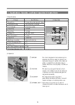
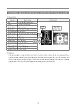
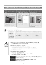
1) Specifications
2) Functions and Operations of Pressure Sensor
After the water begins to be supplied through the inlet
valve of washer, the tub is filled with water. The rising
water level in the tub delivers the head pressure
(mmH20), which passes through the pressure delivery
hose between the tub and pressure sensor to the
enclosed space. The pressure is transmitted to the ®Á
diaphragm, which rises as the pressure increases. The
delivered pressure immediately leads to the ®Ë metal
core. As the metal core rises into the ®ÈCOIL-ASSY
that is rolled in a specific format, the condensers and
resistances connected to IC- 4069 buffer, a frequency
oscillation circuit on C-MOS inverter using the
induced electromotive force and magnetic force according to the contact of coil, are oscillated through RC, which
leads the SIGN wave in frequency from the inductor to pass through the outlet buffer to be transformed into digital
signals and transmit a square wave to display the oscillation cycle in a frequency format.
The frequency signals predetermined in the set play switching functions to control the head pressure in the tub.
After the wash cycle is complete at the preset level and the water is drained, the head pressure declines to return
the metal core to the original condition, enabling the repetitive application of function during the cycle.
5. Specifications, Operation, and Defect Inspection of Water Level Sensor
O/F: Water level at which the water must be drained
due to excessively high level. Water supply is
suspended and water drained until the level drops to the
reset level.
RESET:
1. Drainage level. A spin cycle starts 20 to 40
seconds after the reset level is reached.
Water Level to Tunr off Heater:
1. Water level at which the heater is suspended
Model
Part Code
Category
Reset
Heater Off Lock Off Lock On Wash 1 Wash 2 Water Level
for Rinse Overflow
DWD-M301WP
3614825320
Frequency 25.80KHZ 24.56 KHZ 24.32 KHZ 24.0 KHZ 23.84
KHZ
23.68
KHZ 23.68 KHZ 22.0 KHZ
DWD-M300WA
DL - DW12 - H
Содержание MINI 1.0
Страница 9: ...8 3 COVER BODY AS C01 C05 C08 C06 C02 C03 C04 C07 ...
Страница 11: ...10 4 1 DOOR AS MINI 1 0 D CV701 WFWM11 ...
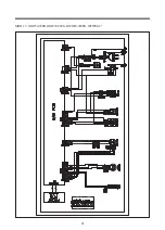
Страница 31: ...30 5 Wiring Diagram D CV701 01 D CV701 ...
Страница 32: ...31 MINI 1 5 ODW30 999B ODW30 999G DWM30 999PG WFWM12 ...
Страница 57: ......


