35
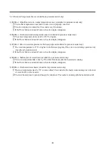
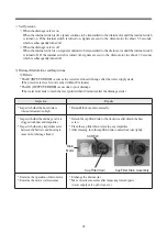
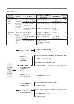
Inspection
Repairs
* Inspect the power connector
* Normalize the connection of connector
* Inspect the connection of hall sensor connector
* Normalize the connection of harness connector
* Inspect the operation of motor
* Assess the resistance in motor coil
* Exchange the motor
* Check the items specified above
* Take corrective measures after inspecting the
corresponding parts (PCB, harness, drum components,
etc.)
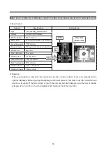
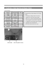
3) Motor Malfunctions and Inspections
◎
Malfunction: * The b8 error (Failure in starting motor) occurs when the power is not supplied or other
malfunction takes place.
* The b8 error occurs even when the motor fails to rotate properly due to defective connection of
connector.
* The b2 error occurs when an excess current (15A or higher) flows into PCB.
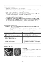
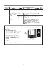
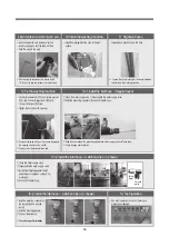
4) Motor Exchange Service
[Disassembly]
1
Separate the power supply device and hall sensor
connector from the motor
2
Separate the belt
3
Disconnect 4 motor-fixing bolts
[Assembly]
Re-assemble the parts in the opposite sequence to
disassembly
□
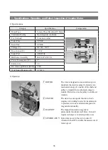
Motor's Functional Mechanism
- The device transforms electric energy into mechanical energy.
- The motor contains a costly auxiliary driving gear, is controlled by semiconductors, causes low electric/
mechanical noises, and is capable of running at high speed.
- The hall IC applies to locate the rotor. It acts as a brush-type commutator.
- The hall IC locates the active rotor with the magnet attached to the rotor and sends signals from the current
rotor location to the base of transistor connected to the coil producing torques.
- TR approved for signals acts as an electronic switch to send the electric current to coil, causing forces (F)
between the field magnet and coil to rotate the rotor.
- As the hall IC detects the pole opposite to the initially detected one when the rotor is running, the initially
started TR is turned off and another TR is turned on to send the electric current in an opposite direction to
the current over coil. This leads to cause the forces (F) between the field magnet and coil consistently.
- The mechanism reiterates to run the motor consistently.
Содержание MINI 1.0
Страница 9: ...8 3 COVER BODY AS C01 C05 C08 C06 C02 C03 C04 C07 ...
Страница 11: ...10 4 1 DOOR AS MINI 1 0 D CV701 WFWM11 ...
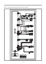
Страница 31: ...30 5 Wiring Diagram D CV701 01 D CV701 ...
Страница 32: ...31 MINI 1 5 ODW30 999B ODW30 999G DWM30 999PG WFWM12 ...
Страница 57: ......


