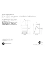
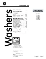
background image

SAFETY SWITCH UNIT
1) CIRCUIT DIAGRAM

2) EXPLANATION OF CIRCUIT

• The MICOM terminal No. 63 gets into 'L' at the state of the closed lid. If the lid is opened in spining stage, the MICOM

generates error signal as 'LE'.

• Case of range 40 mSEC~300 mSEC in spining time: It is regarded that washing clothes should be inclined.

Accordingly washing time increases 8 minutes and rinsing action takes place another one time. Case of above 400
mSEC: It is regarded that the lid should be open. Therefore it is displayed as 'LE'.

3) CAUTION FOR A/S

• Be level with the ground.
• The 'UE' error occurs in case of not being level with the ground.
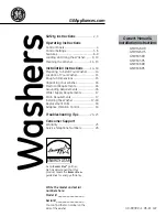
• The waveform between the MICOM terminal No. 63 and the GND.
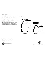
LOAD SENSOR UNIT
1) CIRCUIT DIAGRAM 

2) EXPLANATION OF CIRCUIT

• After TRIAC is off, RUNNING CONDENSOR discharges the voltage charged in it and sinwave is generated at this time.

MICOM starts to check every 0.224ms the time from 2nd falling edge to 3rd falling edge. Photo coupler (IC4) of PCB
converts the sinwave into clock pulse (times X 0.224ms) and send it to MICOM terminal No. 22 & 23. MICOM checks
the clock pulse and counts the periodic time and judges the water level after comparing with data which is already
memorized in the MICOM.

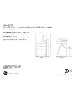
• The waveform between the part of 

!

and GND (Waveform of pulse)

40

R3.220

R4,3.9K

Safety

S/W

C1

104Z

0V

5.4V

t

Lid is closed

Lid is open

M

I

C
O

M

22

23

R13, 220

R14, 220

C12

104Z

R17
10K

Q3

A562

R39,10K

Q16

C1959

!

5.4V

R53, 10K

R55, 10K

PC817

R54

3.9K

1N4148

D5

IC4

6V

TRIAC

MOTOR

RUNNING CONDENSOR

0

5.4V

1st

2nd

3nd

triac on

triac off

(time X 0.224ms)

Содержание DWF-5590DP Series

Страница 1: ...C K28177 8 CABLE DAEWOOELEC FAX 02 364 5588 TEL 02 360 7381 7389 DAEWOO ELECTRONICS CO LTD S M NO WF55900200 PRINTED DATE NOV 1995 Caution In this Manual some parts can be changed for improving their...

Страница 2: ...INSTALL THE DRAIN HOSE FOR DWF 5590D SERIES NON PUMP 15 HOW TO INSTALL THE DRAIN HOSE FOR DWF 5590DP SERIES PUMP 16 HOW TO CLEAN DRAIN FILTER DWF 5590DP SERIES PUMP ONLY 17 6 PROCEDURE OF FULL AUTOMA...

Страница 3: ...4L LOW 36L E LOW 28L 8 OPERATING WATER PRESSURE 0 3 8kg cm2 2 9N cm2 78 4N cm2 9 REVOLUTION PER MINUTE SPIN 775R P M WASH 145R P M FOR 60Hz 10 PULSATOR 6 WINGS 350mm 11 WATER LEVEL CONTROL ELECTRICAL...

Страница 4: ...y while spinning WATER FLOW FUNCTION FOR SOAK WASH DISPLAY THE RESIDUAL TIME When the SOAK WASH is selected the total wash time increases because 30 minutes for soak process are added to the time of m...

Страница 5: ...r the tub wall by rotation on the pulsator B Water is pulled down in the middle of the tub by rotation of the pulsator C Water currents is generated by rotation of the pulsator C Rotate A A B Good dra...

Страница 6: ...s added into the tub through softener outlet FLOW OF THE SOFTENER FLOW OF THE SOFTENER INSIDE OF THE BALANCER NOTE Softener moves into the next room when r p m of the tub is more than 100 r p m HOW TO...

Страница 7: ...IRCULATING WATER COURSE AND LINT FILTER CIRCULATING WATER The washing and rinsing effects have been improved by adopting the water system in which water in the tub is circulated in a designed pattern...

Страница 8: ...ll be counted down according to the process When operation is finished the TIME INDICATOR will light up DRAIN MOTOR STRUCTURE FUNCTIONAL PRINCIPLE 1 When the DRAIN MOTOR connected to the power source...

Страница 9: ...tch spring Brake lever Spinner shaft Planetary gear Clutch spring Clutch boss Spinner pulley Sun gear Internal gear Planetary gear Pulsator Planetary V belt Spinner pulley 1 revolution 5 2 revolutions...

Страница 10: ...ond The magnetic pole of trans core is changed by the change of the phase of A C electric power The core repeats push and pull 3600 times min of the armature magnet FUNCTIONAL PRINCIPLE OF BUBBLE WASH...

Страница 11: ...h and it will be added into the tub automatically just before the final rinse COLD WATER TAP After using the washer close the water tap and turn off the power BLEACH INLET CONTROL PANEL SCREW COVER TU...

Страница 12: ...e course by proper combination with the right three buttons If you want the washer to operate differently from presetting time or to operate separately among the three stages you first push this butto...

Страница 13: ...machine so that it sits HOW TO INSTALL ON AN INCLINED PLACE properly 13 DIRECTION FOR INSTALLATION AND USE Never install in these places The place where it would be exposed to direct sunlight The plac...

Страница 14: ...ap Adapter Rubber packing Connector C Collar Loosen the four screw at the water tap adapter but don t loosen the screws until they are separated from the water tap adapter Connector A Tape Connector B...

Страница 15: ...HE DRAIN HOSE In case that it goes over a doorsill Don t let the height of the drain hose exceed 20cm from the ground In case of extending the drain hose Don t let the total length exceed 3m 20cm 3m B...

Страница 16: ...d of the hose guide This is to prevent SYPHONING If necessary the drain hose can be trimmed to length 16 Connect the drain hose to the drain outlet at the back side of the washing machine and fasten i...

Страница 17: ...the drain filter If you clean the drain filter following above instructions you could continue the normal operation of the washing machine to reset the program please turn the power off and on again...

Страница 18: ...The selection is effective for blue jean climbing clothes ruck sack sports wear etc NIGHT This selection is for a night washing housewife who has no opportunity at day time As far as putting the power...

Страница 19: ...and wash for 6 minutes SPIN RINSE SPIN RINSE SPIN START HOLD Water inlet and wash for 4 minutes SPIN RINSE SPIN RINSE SPIN R L R L R L R L R L Water inlet and wash for 14 minutes SPIN RINSE SPIN RINS...

Страница 20: ...flange nut by using T type box wrench T type box wrench Nut spin shaft fixing Washer Lay the front of the washer on the floor Remove four bolts mounting the plate gear protect by using a box wrench a...

Страница 21: ...ever Tighten the lock nut and apply a small amount of paint lock Brake lever Adjustment bolt Gear mechanism ass y Clutch lever NOTE 1 The brake adjustment has been made at the factory so that it is no...

Страница 22: ...Does the water inlet valve make operating sound Change water inlet valve NO Flow rate min Water pressure kg cm 3 11 5 15 0 18 0 20 3 24 1 27 4 0 3 0 4 0 5 0 6 0 8 1 0 NOTE Open the water tap fully an...

Страница 23: ...ormed Air tube is defective YES Change the air tube Pressure switch is defective NO Change the Pressure switch NO NO YES NO PROBLEM CHECK POINT CAUSE SOLUTION Does the motor operate after finishing wa...

Страница 24: ...the lid open Does the safety switch operate normally Improper connection of the connector Connect the connector properly P C B ASS Y is defective Do you put down the drain hose Does the drain motor o...

Страница 25: ...tate Is the output voltage of the drain motor normal P C B ASS Y is defective Change the P C B ASS Y V belt is defective YES NO Is the V belt worn out Change the motor Motor is defective Is the output...

Страница 26: ...e of the transformer normal P C B ASS Y is defective Change P C B ASS Y PROGRESS LAMPS LED DO NOT LIGHT UP Press START HOLD button NO P C B ASS Y is defective Change P C B ASS Y NO Do you press START...

Страница 27: ...inlet filter clogged Clean the water inlet filter It passes over the 30 minutes yet it doesn t come Check whether or not it comes to the to assigned water level assigned water level Wash loads get un...

Страница 28: ...is not installed ALL LED light 8 times and go back to 3 first stage Times to push DISPLAY FUNCTION the SPIN button 1st time A Pulsator rotate without water in the tub and bubble pump on Drain Spin Co...

Страница 29: ...F1 CF2 VDD P80 AN0 P81 AN1 P82 AN2 P83 NT3 P7 INT0 P71 INT1 P72 INT2 T0IN P73 INT3 T0IN S0 T0 S1 T1 S2 T2 S3 T3 S4 T4 S5 T5 S6 T6 S7 T7 64 63 62 61 60 59 58 57 56 55 54 53 52 51 50 49 48 47 46 45 44 4...

Страница 30: ...power to loads The purpose of using the MICOM terminal No 6 Q15 A1271Y is that the Q15 prevents the instant supply of electric power supply to loads in case MICOM s action is wrong by means of pushing...

Страница 31: ...as TR forces to turn on sufficiently The ceramic condenser C29 between T1 and the GATE of the TRIAC is used for preventing the wrong action by means of the noise The R63 100 1W and C28 683K between th...

Страница 32: ...TRIAC is out of order to begin with check the MICOM terminal No 6 and TR Q15 A1271 necessarily The TRIAC s names and the values of the snubber resistance of the total parts 32 SM12JZ47 12A SM8JZ47 8A...

Страница 33: ...24 and the GND 3 CAUTION FOR A S The output of the frequency in the WATER LEVEL SENSOR varies in accordance with temperature and using condition If it doesn t input the output of the WATER LEVEL SENSO...

Страница 34: ...R 7806 D6 1N4003 104Z C32 C13 3300 F 10V C34 410 F 16V C32 104Z 104Z C31 C33 220 F 35V D5 1N4003 220V COMMON The gray red The waveform in secondary part of the transformer Measuring the waveform in ca...

Страница 35: ...and ceramic condenser have short circuit The reason is that it happerns no electric power supply INTERRUPT UNIT 1 CIRCUIT DIAGRAM 2 EXPLANATION OF CIRCUIT The INTERRUPT UNIT is necessary to reduce th...

Страница 36: ...h all programs are initialized when the power switch is ON Here the reason why uses RESET I C is that the RESET UNIT prevents the MICOM from incorrect action Also R11 C7 104Z as a RC fiter is used in...

Страница 37: ...according to the condenser component of piezoelectric element and R8 remove the phenomenon of abnormal oscillation by preventing the collector floating state of Q1 The waveform in the part of the BUZZ...

Страница 38: ...the button input with getting out the segmental output at the same time RA1 473J 47K is a PULL DOWN resistance for preventing floating action D15 prevents the L E D from turning on unnecessarily with...

Страница 39: ...KHz Crystal Cscillator KF 38G 13P0200 The waveform between the part of and the GND The waveform between the part of and the GND f 12MHz t f 32 768KHz t TYPE OF OSCILLATOR MAKER NAME OF CONDENSER OSCIL...

Страница 40: ...D SENSOR UNIT 1 CIRCUIT DIAGRAM 2 EXPLANATION OF CIRCUIT After TRIAC is off RUNNING CONDENSOR discharges the voltage charged in it and sinwave is generated at this time MICOM starts to check every 0 2...

Страница 41: ...c4 b2 b3 b3 b4 M1 TM M2 REM NA COLD ME HOT SM Lo MI HI BK1 BK2 SKg SKb MD1 MD2 WO1 WO2 ST1 ST2 SD1 SD2 SP1 SP2 F1 F2 10 11 12 13 14 14 15 17 18 9 8 7 6 5 4 3 2 1 9 10 11 12 13 14 15 16 8 7 6 5 4 3 2...

Страница 42: ...of the DUTY is 1 9 And as part of the DUTY treats the black time between the square waves it prevents the phenomenon of faint lighting of L E D unnecessarily due to the phenomenon of fold in delay ti...

Страница 43: ...WIRING DIAGRAM FOR DWF 5590DP SERIES APPENDIX APPENDIX 43...

Страница 44: ...WIRING DIAGRAM FOR DWF 5590D SERIES 44...

Страница 45: ...D 1 COMMON 6670 3610064700 ASSY CAP VALVE HOT 1 COMMON 6670 3619001600 SOL 220V P15 3619002000 SWITCH POWER SOL 240V 1 3619002300 SOL 110V P16 3615403830 VALVE INLET WARM AC 220 240V 50Hz 1 COMMON 667...

Страница 46: ...LTER LINT PP 1 E TYPE B18 3614002000 PACKING NBR 1 E TYPE B19 3616004300 SPECIAL WASHER PE 1 E TYPE B20 3610903800 CAP FILTER PP 1 E TYPE B21 3611109700 CASE FILTER PP 1 E TYPE B22 3611109700 COVER PU...

Страница 47: ...X12 SUS 1 T28 4505E83120 SCREW BASE FIX SM 5X13 2 T29 4505E83100 SPECIAL BOLT BASE 6 5X23 8 T30 3611201000 CLAMP HSW3 D2 6 MFZN 2 T31 3613212100 HOSE DRAIN I LDPE0EVA L 184 1 ONLY T32 3618301300 PROTE...

Страница 48: ......

Страница 49: ......

Страница 50: ......

Страница 51: ...1 COMMON 6670 3610064700 ASSY CAP VALVE HOT 1 COMMON 6670 3619001600 SOL 220V P15 3619002000 SWITCH POWER SOL 240V 1 3619002300 SOL 110V P16 3615403830 VALVE INLET WARM AC 220 240V 50Hz 1 COMMON 6670...

Страница 52: ...4505E32030 SPECIAL SCREW 6X26 5 1 T04 4505E32050 RING O D5 5 1 COMMON 5570 T05 3610055900 PULSATOR AS DWF 5570 1 COMMON 5570 T06 4507D83080 SPECIAL NUT SUS 304 1 COMMON 5570 T07 4509L83070 SPECIAL WAS...

Страница 53: ...618301300 PROTECTOR GEAR SECEN 1 6T 1 ONLY T32 7640061611 BOLT HEX 6B 1 6X16 SW MFZN 2 T33 4507D20011 PULLEY MOTOR ADC 12 DS 10 DP 53 50Hz 1 3618401100 ADC 12 DS 10 DP 48 5 60Hz T34 3616000702 SPECIAL...

Страница 54: ......

Страница 55: ......

Страница 56: ......

Страница 57: ...9101P IC EEPROM ROM 1K TOSHIBA LS DATA SELECT IC3 1S8054HN IC RESET S 8054HN IC4 TPC817C PHOTO COUPLER PC817C IC5 1L7806 IC REGULATOR L7806 LW 4507D72154 HARNESS LEAD A 120MM RWF 660T RA1 RA 84X473J R...

Страница 58: ...Z C CERA SEMI 50V F 0 1MF Z TAPPING C3 CBXF1H104Z C CERA SEMI 50V F 0 1MF Z TAPPING C4 CXCH1H180J C CERA 50V CH 18PF J TAPPING C5 CXCH1H180J C CERA 50V CH 18PF J TAPPING C6 CBXF1H104Z C CERA SEMI 50V...

Страница 59: ...Y Q18 TZTC3202Y TR KTC3202Y AUTO 1959Y D2 DKN4003A DIODE KN4003A AUTO 26MM D5 DKN4148 DIODE KN4148 AUTO 26MM D6 DKN4003A DIODE KN4003A AUTO 26MM D7 DKN4003A DIODE KN4003A AUTO 26MM D8 DKN4003A DIODE K...

Страница 60: ...4 10K OHM J R45 RD 4Z102JK R CARBOM FILM 1 4 1K OHM J R47 RD 4Z331JK R CARBOM FILM 1 4 330 OHM J R48 RD 4Z331JK R CARBOM FILM 1 4 330 OHM J R49 RD 4Z331JK R CARBOM FILM 1 4 330 OHM J R50 RD 4Z331JK R...

Страница 61: ...220 OHM J R67 RD 4Z221JK R CARBON FILM 1 4 220 OHM J R68 RD 4Z221JK R CARBON FILM 1 4 220 OHM J R69 RD 4Z221JK R CARBON FILM 1 4 220 OHM J R70 RD 4Z430JK R CARBON FILM 1 4 43 OHM J 26PITCH R71 RD 4Z4...

Страница 62: ...62 CIRCUIT DIAGRAM...

Страница 63: ...BARE PCB BOTTOM BARE PCB TOP 65 64...

Отзывы: