
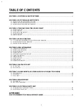


SECTION 3.
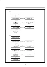
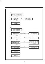
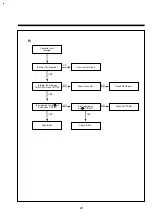
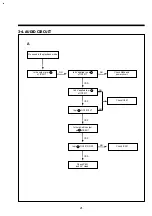
TROUBLE SHOOTING FLOW CHART
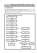
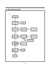
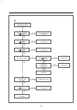
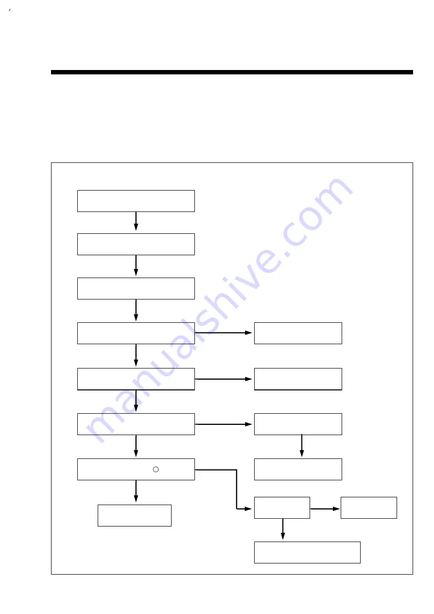
3-1. POWER CIRCUIT
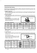
• When change the parts which are out of order, first, remove the power plug from the socket and then discharge the
voltage across between both terminals of C807. (Use an external scores of K
Ω
resistance)
• When check the primary circuit by using the oscilloscopes insulate the oscilloscope surely. (Use the isulating
transformer) and must connect GND into the primary GND), (But there is no connection when check the secondary
circuit).
• When change IC801, check FUSE and Cement resistance surely.
11
Prepare the instrument
connecting the insulating trans.
Check F801 FUSE.
Is voltage applied to D801?
Is voltage applied to the
both terminals of C807?
Check voltage of Q801 Gate.
4
Is voltage output from pin of IC801?
Check Q801.
Check D801, L801 & L802.
Check R802.
Check R803, 805,
814 & 806.
Check Q802, 803,
D802.
Check IC801.
Change IC801.
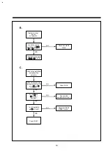
Check the Secondary circuit.
NO
NO
NO
NO
NO
YES
YES
YES
YES
YES
YES
YES
YES
NO output Voltage.
A. CHECKING THE PRIMARY CIRCUIT.
Содержание DV-F24J
Страница 29: ......
Страница 30: ......
Страница 31: ......
Страница 32: ......
Страница 33: ......
Страница 34: ......
Страница 35: ......
Страница 36: ......
Страница 37: ......
Страница 38: ......
Страница 39: ......
Страница 40: ......
Страница 41: ......
Страница 42: ......
Страница 51: ......
Страница 52: ......


