


3. Location of Users Controls
DV-135
-. Rear Panel
1. FM ANTENNA connector
2. AM ANTENNA connectors
3. DIGITAL INPUT OPTICAL jack
4. DIGITAL INPUT COAXIAL jack
5. DIGITAL OUTPUT OPTICAL jack
6. PRE OUT SUBWOOFER jack
7. MONITOR OUT jack
8. S VIDEO MONITOR OUT jack
9. COMPONENT VIDEO OUTPUT Y/Cb/Cr jacks
10. Power cord
11. CENTER SPEAKER connectors
12. SURROUND SPEAKERS connectors
13. FRONT SPEAKERS connectors
14. TV IN jacks
15. TAPE/MD IN PLAY(IN)/REC(REC) jacks
16. VIDEO 2 IN jacks
17. VIDEO 1 PLAY(IN)/REC(OUT) jack
18. AC outlet(Option)
-. Display
1. SURROUND MODE indicator
2. RDS indicator
3. PROGRAM indicator
4. STEREO indicator
5. DYNAMIC RANGE indicator
6. TUNED indicator
7. PBC(Playback Control) indicator
8. MEMORY indicator
9. MP3 indicator
10. PRESET indicator
11. REPEAT indicator
12. RANDOM indicator
13. SLEEP indicator
14. PLAY indicator
15. DVD/VCD/CD indicator
16. PAUSE indicator
17. MULTI FUNCTION indicator
18. SPEAKER CONFIGURATION indicator
7
Содержание DV-135
Страница 1: ...DV 135 Digital Home Cinema System ...
Страница 5: ...2 Specifications DV 135 5 ...
Страница 9: ...4 Connecting to Equipment DV 135 Connecting to TV Scart Cable Optional 9 ...
Страница 19: ......
Страница 20: ......
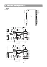
Страница 21: ...8 Internal Block Diagram of ICs DV 135 AK 4112A 21 ...
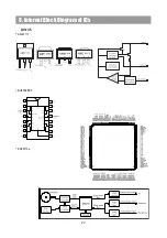
Страница 22: ...8 Internal Block Diagram of ICs DV 135 AME1117 BU4052BCF ZR36710a 22 ...
Страница 23: ...8 Internal Block Diagram of ICs DV 135 CS4228A ZR36701 23 ...
Страница 25: ...8 Internal Block Diagram of ICs DV 135 CXP82852 25 ...
Страница 27: ...8 Internal Block Diagram of ICs DV 135 LA7952 NJM2068 NJU7313A 27 ...
Страница 30: ...10 Block Diagram 30 DV 135 ...
Страница 31: ...DV 135 11 Wiring Diagram 31 ...
Страница 32: ... LEVEL Diagram 12 Level Diagram 32 DV 135 ...
Страница 34: ...13 Schematic Diagram 34 DV 135 DSP 1 ...
Страница 35: ...13 Schematic Diagram DV 135 DSP 2 35 ...
Страница 36: ...13 Schematic Diagram DV 135 DSP 3 36 ...
Страница 37: ...13 Schematic Diagram DV 135 MPEG 37 ...
Страница 38: ... Main Schematic Diagram 1 Power Schematic Diagram 13 Schematic Diagram 38 ...
Страница 39: ... Main Schematic Diagram 2 Amp Schematic Diagram 13 Schematic Diagram 39 ...
Страница 40: ... Main Schematic Diagram 3 Input Schematic Diagram 13 Schematic Diagram 40 ...
Страница 41: ... Main Schematic Diagram 4 Video Schematic Diagram 13 Schematic Diagram 41 ...
Страница 42: ...1 2 BOTTOM View Front PCB 1 1 TOP View 14 Printed Circuit Diagram 42 DV 135 Front PCB ...
Страница 43: ...2 BOTTOM View DSP PCB 1 TOP View 14 Printed Circuit Diagram 43 ...
Страница 44: ...2 BOTTOM View MPEG PCB 1 TOP View 14 Printed Circuit Diagram 44 ...
Страница 45: ...DV 135 MAIN PCB 14 Printed Circuit Diagram 45 ...
Страница 46: ...2 BOTTOM View DV 135 MIC PCB 1 TOP View 14 Printed Circuit Diagram 46 ...
Страница 47: ...15 Mechanism NO Q ty Description PART NAME Hexagon Ni Coated Ni Coated Ni Coated 47 DV 135 ...
Страница 48: ...16 Exploded View and Mechanical Parts List 48 DV 135 ...
Страница 50: ...16 Exploded View and Mechanical Parts List DV 135 50 ...