


17
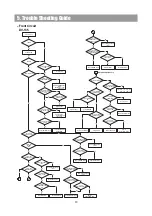
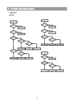
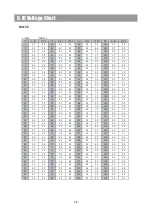
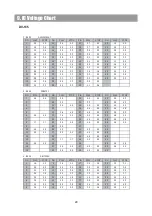
5. Trouble Shooting Guide
DV-135
PICK-UP unit control
Abnormal
Check if the CN706
is OK.
Check if the ATAPI Cable
is normally.
Check if the
PN302
PINS(1)(2)(5)(6) level is
OK.
Check if the PN302
PIN(3) is OK.
Check if the IC102
PIN165 is OK.
Check PATTERN Open
or Short.
Refer to IC102 (MT1388) or
Replace DECK MECHA DVD.
Check Power Supply Circuit.
Reconnect it.
Check if the IC302
PINS(1)(23) is OK.
Refer to IC302(BA5954FN) or
Replace DECK MECHA DVD.
Check if the IC102
PINS(17)(18) is OK.
Check PATTERN Open
or Short.
Replace DECK MECHA DVD.
Refer to IC102 (MT1388) or
replace DECK MECHA DVD.
Yes
Yes
Yes
Yes
Yes
Yes
Yes
No
No
No
No
No
No
No
DISC READ Abnormal
Check if the CN706 is
OK.
Check if the ATAPI Cable
is normally.
Refer to PICK-UP Unit or
Replace DECK MECHA DVD.
Check POWER SUPPLY
circuit.
Refer to IC302(BA5954FN) or
Replace DECK MECHA DVD.
Reconnect it.
Yes
Yes
No
No
Check if the IC302
PINS(1)(26) is OK.
Refer to IC102(MT1388).
Replace DECK MECHA DVD.
No
Yes
Check if the PN301
PINS(1)(2)(3)(4) is OK.
Yes
No
VIDEO OUT Abnormal
Check if the PN401
is normally.
Check if the IC410
PINS(39)(40)(43)(44)(47)
(48) is OK.
Check VIDEO PCB.
Check if the IC410
PIN(1) to (8) is OK.
Check DECK MECHA DVD or
MPEG PCB.
Replace DECODER IC
CS4955.
Reconnect it.
No
No
No
Yes
Yes
Yes
-. Audio Part
Содержание DV-135
Страница 1: ...DV 135 Digital Home Cinema System ...
Страница 5: ...2 Specifications DV 135 5 ...
Страница 9: ...4 Connecting to Equipment DV 135 Connecting to TV Scart Cable Optional 9 ...
Страница 19: ......
Страница 20: ......
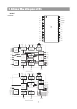
Страница 21: ...8 Internal Block Diagram of ICs DV 135 AK 4112A 21 ...
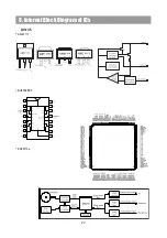
Страница 22: ...8 Internal Block Diagram of ICs DV 135 AME1117 BU4052BCF ZR36710a 22 ...
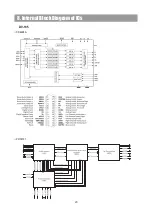
Страница 23: ...8 Internal Block Diagram of ICs DV 135 CS4228A ZR36701 23 ...
Страница 25: ...8 Internal Block Diagram of ICs DV 135 CXP82852 25 ...
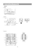
Страница 27: ...8 Internal Block Diagram of ICs DV 135 LA7952 NJM2068 NJU7313A 27 ...
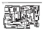
Страница 30: ...10 Block Diagram 30 DV 135 ...
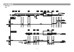
Страница 31: ...DV 135 11 Wiring Diagram 31 ...
Страница 32: ... LEVEL Diagram 12 Level Diagram 32 DV 135 ...
Страница 34: ...13 Schematic Diagram 34 DV 135 DSP 1 ...
Страница 35: ...13 Schematic Diagram DV 135 DSP 2 35 ...
Страница 36: ...13 Schematic Diagram DV 135 DSP 3 36 ...
Страница 37: ...13 Schematic Diagram DV 135 MPEG 37 ...
Страница 38: ... Main Schematic Diagram 1 Power Schematic Diagram 13 Schematic Diagram 38 ...
Страница 39: ... Main Schematic Diagram 2 Amp Schematic Diagram 13 Schematic Diagram 39 ...
Страница 40: ... Main Schematic Diagram 3 Input Schematic Diagram 13 Schematic Diagram 40 ...
Страница 41: ... Main Schematic Diagram 4 Video Schematic Diagram 13 Schematic Diagram 41 ...
Страница 42: ...1 2 BOTTOM View Front PCB 1 1 TOP View 14 Printed Circuit Diagram 42 DV 135 Front PCB ...
Страница 43: ...2 BOTTOM View DSP PCB 1 TOP View 14 Printed Circuit Diagram 43 ...
Страница 44: ...2 BOTTOM View MPEG PCB 1 TOP View 14 Printed Circuit Diagram 44 ...
Страница 45: ...DV 135 MAIN PCB 14 Printed Circuit Diagram 45 ...
Страница 46: ...2 BOTTOM View DV 135 MIC PCB 1 TOP View 14 Printed Circuit Diagram 46 ...
Страница 47: ...15 Mechanism NO Q ty Description PART NAME Hexagon Ni Coated Ni Coated Ni Coated 47 DV 135 ...
Страница 48: ...16 Exploded View and Mechanical Parts List 48 DV 135 ...
Страница 50: ...16 Exploded View and Mechanical Parts List DV 135 50 ...