18 of 29
New Hydraulic Systems
Systems Operation
Valve Operation
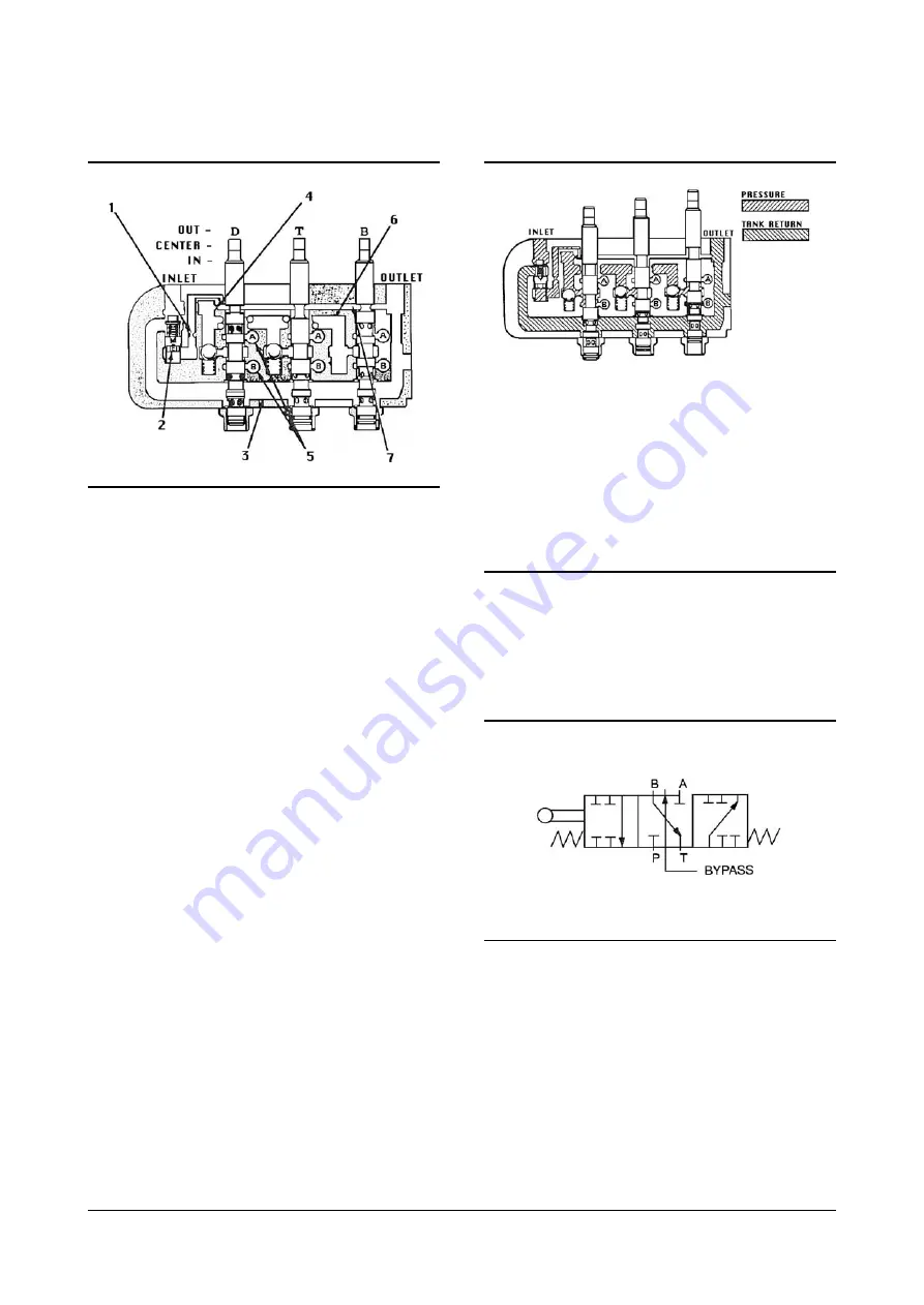
Figure IDCS007B is a schematic illustration of a
three section valve, showing the inlet and outlet ports
and the by-pass, pressure and tank passages.
The pressure passage is used to carry fluid to the
cylinder ports when the spools are shifted. The by-
pass passage permits flow directly to the outlet when
the spools are not being operated. The tank passage
also carries fluid to the outlet; either return flow from
the cylinder ports or fluid diverted past the flow
control and relief valve,
The spools are shown in the centered or neutral
position, Under these conditions, fluid in the pressure
passage is blocked from the cylinder ports by the
spool lands. Flow through the valve is through the
by-pass and tank passages to the outlet.
(1) Control Valve Sensing Orifice.
(2) Flow Control And Relief Valve.
(3) Tank Passage.
(4) By-pass Flow Control Orifice.
(5) Cylinder Ports.
(6) Pressure Passage. (7) By-pass Passage.
IDCS007B
Lift Spool
IN
Pressure to
“
B
”
“
A
”
to tank
By-pass blocked
CENTER
“
A
”
and
“
B
”
blocked
By-pass open
OUT
“
B
”
to tank
“
A
”
blocked
By-pass open
Lift spool - used for control of single acting cylinder
applications. It directs flow to only one end of a
cylinder, as in the lift mechanism of a lift truck.
Return flow is from the same end of the cylinder and
relies on gravity or mechanical means to retract.
IDCS008B
IDCS009B
Содержание D20S-2
Страница 8: ......
Страница 13: ......
Страница 24: ...27 of 29 New Hydraulic Systems Disassembly and Assembly IDCS015B...


