Service manual SC-150
-47-
5-3 Video - VCT description
5-3-1 Introduction
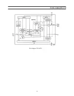
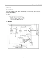
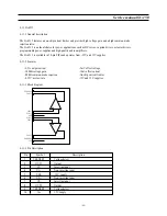
The VCT 38xxA includes complete video, display, and deflection processing.
All processing is done digitally, the video front-end and video back-end are interfacing to the analogue world.
Most functions can be controlled by software via I 2 C bus slave interface.
5-3-2 Video Front-end
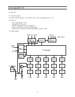
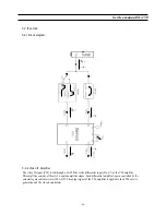
This block provides the analogue interfaces to all video inputs and mainly carries out analogue-to-digital conversion for
the following digital video processing. Most of the functional blocks in the front-end are digitally controlled (clamping,
AGC, and clock-DCO). The control loops are closed by the Fast Processor (‘FP’) embed
ded in the video decoder.
5-3-3 Input Selector
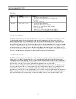
Up to seven analogue inputs can be connected. Four inputs are for input of composite video or S-VHS luma signal.
These inputs are clamped to the sync back porch and are amplified by a variable gain amplifier. Two chroma inputs can
be used for connection of S-VHS carrier-chrominance signal. These inputs are internally biased and have a fixed gain
amplifier.
5-3-4 Clamping
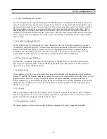
The composite video input signals are AC-coupled to the IC. The clamping voltage is stored on the coupling capacitors
and is generated by digitally controlled current sources. The clamping level is the back porch of the video signal.
S-VHS chrominance is also AC-coupled. The input pin is internally biased to the center of the ADC input range. Each
channel is sampled at 10.125 MHz with a resolution of 8 bit.
5-3-5 Automatic Gain Control
A digitally working automatic gain control adjusts the
magnitude of the selected baseband.
5-3-6 Digitally Controlled Clock Oscillator
The clock generation is also a part of the analogue front-end. The crystal oscillator is controlled digitally by the control
processor. The clock frequency can be adjusted within
±
150 ppm. This adjustment is done in factory for every TV set.
5-3-7 Analogue Video Output
The input signal of the Luma ADC is available at the analogue video output pin (#11). The signal at this pin is buffered
by a source follower. The output voltage is 2 V. The magnitude is adjusted with an AGC in 8 steps together with the
main AGC.
Содержание CHASSIS : SC-150 Model : DSC-3220E
Страница 35: ...Service manual SC 150 34 Block diagram TDA6107Q...
Страница 44: ...Service manual SC 150 43 5 Circuit description 5 1 Block diagram...
Страница 62: ...Service manual SC 150 61 5 9 2 2 STR F6654 oscillating operation...
Страница 82: ...Service manual SC 150 81 8 1 PCB MAIN...
Страница 83: ...Service manual SC 150 82 8 2 PCB UNION...
Страница 84: ...Service manual SC 150 83 9 1 Schematic Diagram MAIN...
Страница 85: ...Service manual SC 150 84 9 2 Schematic Diagram UNION...
Страница 86: ......


