Service manual SC-150
-3-
Fo
5-4-1 Introduction........................................................................................................................................... 51
5-4-2 CPU ...................................................................................................................................................... 51
............................................................................... 52
5-4-4 Tuning .................................................................................................................................................. 52
5-4-5 Automatic
rmat switching and WSS ............................................................................................... 52
5-4-6 EXTERNAL source control logic
........................................................................................................... 54
5-4-7 Over Current Protection
........................................................................................................................ 55
5-5Teletext Display ................................................................................................................................................. 55
5-6 Sound processing
............................................................................................................................................... 56
5-6-1 Analogue sound IF-input section
............................................................................................................ 56
5-6-2 Quadrature Mixers ........................................................................................................... ..................... 56
5-6-3 Phase and AM discr imination........................................................................................................... 56
5-6-4 NICAM decoder.................................................................................................................................... 57
5-6-5 DSP section.......................................................................................................................................... 57
5-6-6 Sound Mode switching.......................................................................................................................... 57
5-7 Sound amplification........................................................................................................................................... 57
5-7-1 Power amplifier..................................................................................................................................... 57
5-7-2 Mode selection....................................................................................................................................... 58
5-8 Vertical deflection............................................................................................................................................. 58
5-8-1 Flyback voltage..................................................................................................................................... 58
5-8-2 Protection.............................................................................................................................................. 58
5-8-3 Guard circuit.......................................................................................................................................... 58
5-8-4 Damping resistor................................................................................................................................... 58
5-8-5 EAST-WEST Amplifier (TDA8358J only)............................................................................................... 58
5-9 Power supply (STR F6653)
.. .............................................................................................................................. 59
5-9-1 STR-F6654 gener
aral description......................................................................................................... 59
5-9-2 Power supply primary par t operations
................................................................................................... 59
5-10TV start-up, TV normal run and stand by mode operations
............................................................................... 63
5-10-1 TV start-up operations .......................................................................................................................... 63
5-10-2 TV normal run and stand-by mode operations
....................................................................................... 64
6 - Se
6 -1 Service part list
rvice parts list..................................................................................................................................................
...........................................................................................................................................
. 69
69
6 -2 Service part list option ............................................................................................................................... 79
7 - Exploded View ........................................................................................................................................................ 80
........................................................................................................................................................ 81
........................................................................................................................................................ 83
8 - PCB Layout
................................................................................................................................................... 81
8 -1 MAIN PCB
................................................................................................................................................... 82
8 -2 UNION PCB
9 - Circuit Diagram
.................................................................................................................................... 83
9 - 1 Circuit Diagram(MAIN)
.................................................................................................................................. 84
9 - 2 Circuit Diagram(UNION)
5-4-3
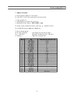
-Controller I/O pin configuration and function
5-3-17 Analogue RGB Insertion ..................................................................................................................... 50
5-3-18 Fast-Blank Monitor .....................................................................................................
........................... 50
5-3-19 Vertical and East/West Deflection ....................................................................................
................... 50
5-3-20 EHT Compensation ........................................................................................................
........................ 51
5-3-21 Reset Function .........................................................................................................
............................. 51
5-3-22 Standby and Power-On ..................................................................................................
...................... 51
5-4 Micro-controller ...............................................................................................................
.......................................... 51
Содержание CHASSIS : SC-150 Model : DSC-3220E
Страница 35: ...Service manual SC 150 34 Block diagram TDA6107Q...
Страница 44: ...Service manual SC 150 43 5 Circuit description 5 1 Block diagram...
Страница 62: ...Service manual SC 150 61 5 9 2 2 STR F6654 oscillating operation...
Страница 82: ...Service manual SC 150 81 8 1 PCB MAIN...
Страница 83: ...Service manual SC 150 82 8 2 PCB UNION...
Страница 84: ...Service manual SC 150 83 9 1 Schematic Diagram MAIN...
Страница 85: ...Service manual SC 150 84 9 2 Schematic Diagram UNION...
Страница 86: ......


