background image

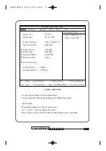
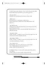
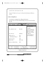
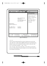
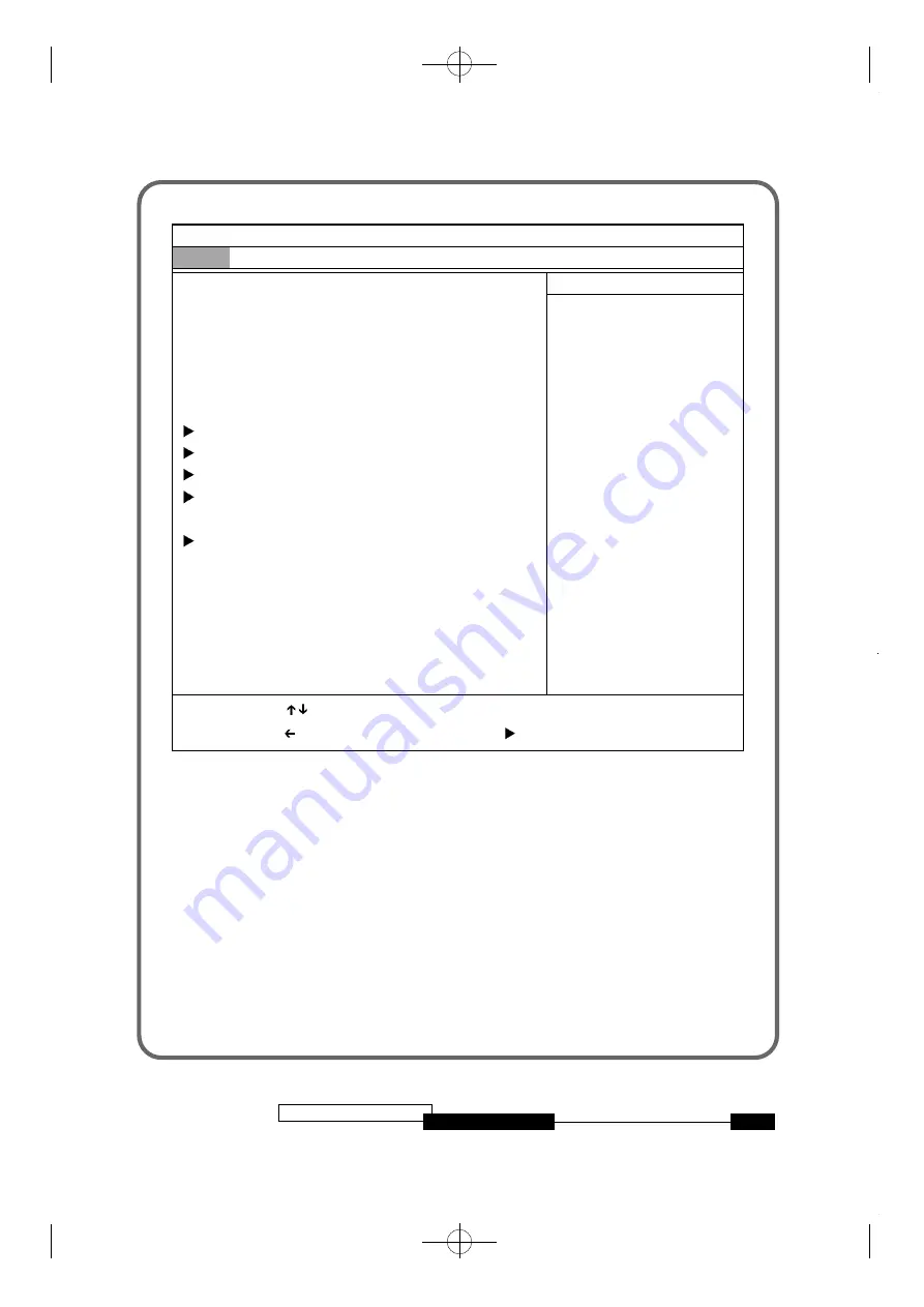
<Figure1> Main Screen

Use this menu for basic system configuration.
You can make the following selections on the Main Menu itself.

-System Ti m e
This option displays the current system time.
Use <+> and <-> keys to change the values.
P ress <Enter> to move from the Hour to the Minute to the second field.

U s e r ’ s   M a n u a l

2 7

C B 6 5 6 M - W H / W L

Phoenix BIOS Setup Utility

M a i n

A d v a n c e d

S e c u r i t y

P o w e r

B o o t

E x i t

System Time :

[ 1 2 : 0 0 : 1 3 ]

System Date  :

[ 0 1 / 0 1 / 1 9 9 8 ]

Legacy Diskette A :

[1.44/1.25 MB 3

1

/

2

” ]

Legacy Diskette B :

[ D i s a b l e d ]

Primary Master

[ 1 7 5 5 M B ]

Primary Slave

[ 3 2 2 9 M B ]

Secondary Master

[ C D - R O M ]

Secondary Slave

[ N o n e ]

Keyboard Features

System Memory

:

6 4 0 K B

Extended Memory :

30720 KB

F 1

Help                Select Item

-/+  Change Values                 F9 Setup Defaults

E s c

Exit                  Select Menu

Enter  Select    Sub-Menu       F10   Save and Exit

Item Specific Help
<Tab>, <Shift-Tab>, or
<Enter> selects field.

CB656M-WH/WL(2)  00.5.12 2:13 PM  

‰¿Ã¡ˆ27

Содержание CB656M-WH

Страница 1: ...DIMMs 13 Install the CPU 13 1 Install the CPU 13 Connect Cables 15 1 CPU Fan connector 15 2 Primary Secondary IDE Connectors 15 3 FDD connector 15 4 IR Connectors 15 5 Wake On Lan Connector 15 6 Front Panel Switch connector 16 7 Power Switch Connector 17 External Connectors 18 1 PS 2 Keyboard Mouse Connector 18 2 Serial Port COM1 and COM2 18 3 Parallel Port Printer Connector 18 4 VGA PORT 19 CONTE...

Страница 2: ...iver CD 20 2 Installing the inf update utility 20 3 Installing the VGA driver from CD ROM 21 4 AC97 Audio WDM driver installation 23 3 Setup 1 MAIN Setup Menu 26 2 Advanced Setup Menu 29 3 Security Setup Menu 31 4 Power Setup Menu 34 5 Boot Setup Menu 36 6 Exit Setup Menu 38 CB656M WH WL 1 00 5 12 2 13 PM Ã ˆ2 ...

Страница 3: ... standard 168 pin unbuffered DIMM Sockets with memory size up to 512MB using 128Mb DRAM Technology support Synchronous DRAM modules CB656M WH WL have GMCH Graphic Memory Controller Hub GMCH integrates a 66 100Mhz bus controller integrated 2D 3D graphics accelelator 100Mhz SDRAM controller and a high speed hub interface for communication with ICH ICH0 The ICH ICH0 integrates an Ultra ATA 33 ICH0 or...

Страница 4: ...B 256MB with 64MB 128MB SDRAM technology Support 4MB Display cache GMCH only Hub interface for access to the ICH ICH0 2 2 I O Controller Hub ICH ICH0 PCI 2 2 interface Bus master interface USB controller SMBus controller FWH interface U s e r s M a n u a l 4 CB656M WH WL Caution There is the danger of an explosion if the battery is incorrectly replaced Replace the battery with the same or equivale...

Страница 5: ...AM Module 5 Low Pin Count LPC Interface The ITE8712 8702 super I O migrated to the Low Pin Count LPC interface Standard I O Functions One floppy disk drive connector One SPP EPP ECP Compatible Parallel Port Two 16C550 Compatible Serial Port Game port MPU 401 interface 6 Expansion Slots Three 32 bit PCI slots all support PCI master PCI specification version 2 2 compliant One AMR connector U s e r s...

Страница 6: ...t serial port 9 pin D Sub USB ports Fully supports Universal Host Controller Interface UHCI and uses UHCI compatible software drivers 8 IDE Support Provide two independent bus mastering PCI IDE interfaces Primary and Secondary IDE ICH0 Support PIO Mode 4 transfer up to 14MB s and Ultra DMA 33 33MB s and ICH support up to Ultra DMA 66 The BIOS automatically detects the IDE device transfer rate and ...

Страница 7: ... Integrated hardware motion compensate engine 4MB Display Cache GMCH only 12 Power on function Power button on Keyboard password power on Hotkey power on PC98keyboard Power on 13 Hardware monitoring Integrated ITE8712 hardware monitor Supports two FAN speedmonitoring and voltage monitoring U s e r s M a n u a l 7 CB656M WH WL CB656M WH WL 2 00 5 12 2 13 PM Ã ˆ7 ...

Страница 8: ...6 MODEL 1 Floppy cable CB656M WH WL User s Manual Device driver CD 1 Serial cable option Installation Steps Installing of the CB656M WH WL motherboard depends on the type of case you use The CB656M WH WL motherboard is designed for the ATX form factor and must be installed in an ATX chassis Before using your computer you must complete the following steps U s e r s M a n u a l 8 CB656M WH WL 2 Inst...

Страница 9: ...dware settings are made through the use of jumper cap to connect jumper pins on the motherboard Refer to motherboard layout on following page The jumper settings will be described numerically such as 1 2 2 3 or On Short Off Open U s e r s M a n u a l 9 CB656M WH WL CB656M WH WL 2 00 5 12 2 13 PM Ã ˆ9 ...

Страница 10: ...ips To protect them against damage from static electricity you should follow some precaution whenever you work on your computer 1 Unplug your computer when working on the inside 2 Use a grounded wrist strap before handling computer components If you do not have one touch both of your hands to a safely grounded object or to a metal object such as the power supply case 3 Hold components by the edges...

Страница 11: ... Password function is available from setting this jumper See detailed information on BIOS setup Security menu U s e r s M a n u a l 1 1 CB656M WH WL KEYBOARD VOLTAGE NORMAL PASSWORD FUNCTION JP34 1 2 2 3 MEMORY VOLTAGE NORMAL JP6 1 2 3 4 5 6 CB656M WH WL 2 00 5 12 2 13 PM Ã ˆ11 ...

Страница 12: ...de should be trouble free Caution Use Only PC 100 SDRAM Module Unplug the power cord from the wall when installing memory 2 Memory Configuration The following table lists a number of possible memory configurations Table 2 2 CB656M WH WL Memory Configurations U s e r s M a n u a l 1 2 CB656M WH WL On Board Audio Codec Enable Disable JP5 2 3 1 2 DIMM TOTAL DIMM1 8MB 16MB 32MB 64MB 128MB DIMM2 8MB 16...

Страница 13: ... down until it locks into place past the release tabs Figure 2 1 Installing a 168 pin DIMM To remove DIMMs follow the steps below 1 With both thumbs or fingers press the release tabs away from the socket 2 With the DIMM free from the release tabs lift the memory module up and place in the anti static bag or package Installing the CPU The CB656M WH WL is designed to support Intel Celeron CPU 1 Inst...

Страница 14: ...on of CPU and ZIF socket lift the lever up to the top put the CPU onto the socket and lay down the lever of socket and then lock the lever of socket Install the CPU U s e r s M a n u a l 1 4 CB656M WH WL CB656M WH WL 2 00 5 12 2 13 PM Ã ˆ14 ...

Страница 15: ... the other end to your hard disk drive s 3 FDD connector J13 This connector supports the provided 34 pin ribbon cable After connecting the single end to the motherboard connect the two plugs on the other end to the floppy drives 4 IR connectors J33 CB656M WH WL provide connectors which can support Standard IrDA InfraRed Data Association receiver module It gives users IR wireless data exchange dire...

Страница 16: ...nd Key Lock 12 22 1 11 U s e r s M a n u a l 1 6 CB656M WH WL PIN 1 2 3 Signal Name 5V Standby Ground WOL Pin number Pin 1 Pin 2 Pin 3 Pin 4 Pin 5 Pin 6 Pin 7 Pin 8 Pin 9 Pin 10 Pin 11 Description Power GND Green LED Power Button GND GREEN LED GND POWER HDD LED GND H W RESET Pin number Pin 12 Pin 13 Pin 14 Pin 15 Pin 16 Pin 17 Pin 18 Pin 19 Pin 20 Pin 21 Pin 22 Description Power N C GND Keylock GN...

Страница 17: ...ge the system from Normal operation mode to Suspend mode Pushing the button again will wake up the system 2 Pushing the power button more than 4 seconds will shut down the system Disabled Pushing the power button one time will turn the system on pushing again will turn the system off 8 ATX Power Supply Connector J25 This connector connects to an ATX power supply The plug from the power supply will...

Страница 18: ...J10 J11 The CB656M WH WL provides two sets of high speed serial port Each serial port is 16550 UART compatible One is 9 pin D sub connector and the other is 10 pin header for optional serial port cable 3 Parallel Port Printer Connector J9 The CB656M WH WL provides one set of high speed parallel port The parallel port can support bi direction EPP ECP mode Figure 2 2 External connectors U s e r s M ...

Страница 19: ... that outline to the operating system how the chipset components shall be configured for proper functionality of the following features Core PCI and ISAPNP Services AGP Support IDE ATA33 ATA66 Storage Support USB Support Identification of Intel Chipset Components in Device Manager Files for Windows 98 operating system and files for Windows 95 operating system are included in this software package ...

Страница 20: ...TUP EXE 5 You will be prompted to agree to the license agreement If you do not agree the Installer will exit prior to extracting any files 6 The INF files will be copied to the target directory C Program Files Intel IntelINF by default If desired change the target directory by selecting Browse This directory will henceforth be referred to as INF Installation Directory 7 The INF files are now conta...

Страница 21: ... Directory 6 Follow the screen instructions and use default settings to complete the setup once the operating system has rebooted 7 At this point the installation of the INF Update Utility for Intel r Chipsets is complete 3 INSTALLING THE VGA DRIVER FROM CD ROM 1 Select My Computer icon Control Panel icon and then the Display icon 2 You should now be in the Display Properties window Select the Set...

Страница 22: ...ry from the Graphics subdirectory and then enter the directory for the language you wish to install see language abbreviation section 2 At this point you should see the i81xw9x inf file highlighted click OK 8 Click OK The select Device screen should open and may have two options to choose from some systems could have only one Select Intel 82810 DC100 Graphics Controller Hub if you have a system wi...

Страница 23: ...ew Hardware Wizard This wizard searches for new drivers for PCI Multimedia Device Select next 11 Ensure that the following choice is selected Search for the matching driver for your device recommended 12 Select next 13 Windows98 will list locations from where the updated driver file can be found Ensure that the following choice is selected Specify a location 14 In the specify a location dialog box...

Страница 24: ...xt 16 Windows 98 should display that the following driver has been found 82801AA AB AC 97 Audio Controller 17 Select Next 18 Select Finish U s e r s M a n u a l 2 4 CB656M WH WL CB656M WH WL 2 00 5 12 2 13 PM Ã ˆ24 ...

Страница 25: ...nging Saving SETUP 1 SETUP can be invoked when the power is turned on or software reset is initiated During the initial boot sequence Press F2 will display the setup main screen 2 From the initial SETUP menu use arrow key Right or Left to display the next or previous menu There are six SETUP menus and they are Main Advanced Security Power Boot Exit 3 To select an option entry press arrow key Up or...

Страница 26: ...UP menu 2 Press ESC to go to the Exit menu 3 On the Load Setup Defaults option press Enter and select Yes 4 Select the Exit Saving Changes to save the default values and exit SETUP Next sections provide explanation of the SETUP configurations 1 MAIN Setup Menu To start Phoenix BIOS Setup utility 1 Turn on or reboot your system Phoenix BIOS displays this message Press F2 to enter SETUP 2 Pressing F...

Страница 27: ...hoenix BIOS Setup Utility Main Advanced Security Power Boot Exit System Time 12 00 13 System Date 01 01 1998 Legacy Diskette A 1 44 1 25 MB 31 2 Legacy Diskette B Disabled Primary Master 1755MB Primary Slave 3229MB Secondary Master CD ROM Secondary Slave None Keyboard Features System Memory 640KB Extended Memory 30720 KB F1 Help Select Item Change Values F9 Setup Defaults Esc Exit Select Menu Ente...

Страница 28: ...boot up The user can define its own parameter by selecting the User value If you press Enter the screen displaying data for each device will appear Keyboard Features Specify Keyboard Features as Following Num Lock On or Off turns NumLock on or off at bootup Auto turns NumLock on if it finds a numeric key pad Key Click Turns audible key clik on Keybord auto repeat rate Sets the number of times a se...

Страница 29: ... to incorrect values may cause your system to malfunction Installed O S Win 98 Win 2000 Reset Configuration Data No PS 2 Mouse Auto Detect Secured Setup Configurations No Large Disk Access Mode DOS Local Bus IDE adapter Both Spread Spectrum Enabled I O Device Configuration Advanced Chipset Control F1 Help Select Item Change Values F9 Setup Defaults Esc Exit Select Menu Enter Select Sub Menu F10 Sa...

Страница 30: ...enable the PS 2 mouse only if present Secured Setup Configurations Yes prevents the Operaing System from overriding selections you have made in setup Large Disk Access Mode Select DOS if you have DOS Select Other if you have another operating system such as UNIX A large disk is one that has more than 1024 cylinders more than 16 heads or more than 63 tracks per sector Local Bus IDE adapter Enable t...

Страница 31: ...you want to disable onboard video controller Selsct Disable Onboard Video Then no system memory will be allocated for video Enable memory Hole If enabled turn system RAM off to free address space for use with an option card Either a 16KB conventional CD hole starting at 880KB DC000h or a 1MB extended memory gap starting at 15MB will be created in system RAM Frequently Ratio Select the internal fre...

Страница 32: ...B656M WH WL PhoenixBIOS Setup Utility Main Advanced Security Power Boot Exit F1 Help Select Item Change Values F9 Setup Defaults Esc Exit Select Menu Enter Select Sub Menu F10 Save and Exit Supervisor Password Is Clear User Password Is Clear Set Supervisor Password Enter Set User Password Enter Password on boot Disabled Diskette access Supervisor Fixed disk boot sector Normal Virus check reminder ...

Страница 33: ... transmit system files of the hard disk or to format the hard disk Virus check reminder If Daily Weekely or Monthly is selected the system prompts the user with reminder for virus check at respective intervals System backup reminder If Daily Weekely or Monthly is selected the system prompts the user with reminder for system backup at boot up Power Supply Control This item allows you to select a me...

Страница 34: ...hoenixBIOS Setup Utility Main Advanced Security Power Boot Exit F1 Help Select Item Change Values F9 Setup Defaults Esc Exit Select Menu Enter Select Sub Menu F10 Save and Exit PowerButton Override Enabled Power Savings Disabled Standby Timeout Off Auto Suspend Timeout Off Resume On Time Off Resume Time 00 00 00 Resume On Modem Ring Off Item Specific Help Enabled Use PowerButton as the Suspend Res...

Страница 35: ...e Power Button as Softoff Button Power Savings Specify Power Savings option as following Maximum Power Saving Conserves the greatest amount of system power Standby Timeout 1 Minute Auto Suspend Timeout 5Minutes Maximum Performance Conserves power but allows greatest system performance U s e r s M a n u a l 3 5 CB656M WH WL CB656M WH WL 2 00 5 12 2 13 PM Ã ˆ35 ...

Страница 36: ...he pre set the system recovers from the Suspend mode Enabled wakes the system up at a specific time Resume Time Define the Resume Time when Resume On Time is set to On Resume On Modem Ring Enabled wakes the system up when an incoming call is detected on your modem 5 Boot Setup Menu Use this menu to specify any drive as a boot drive Selecting Boot from the Menu Bar displays the Boot menu which look...

Страница 37: ...evices use the sub menus to specify which one to use on the boot order list as described in the following PhoenixBIOS Setup Utility Main Advanced Security Power Boot Exit F1 Help Select Item Change Values F9 Setup Defaults Esc Exit Select Menu Enter Select Sub Menu F10 Save and Exit 1 Removable Devices 2 Hard Drive 3 ATAPI CD ROM Drive 4 Network Boot Hard Drive Removable Devices QuickBoot Mode Ena...

Страница 38: ...ces from the Boot Menu Select the removable device to use for booting by using the up and down arrows Then move it to the top of this list using the key QuickBoot Mode By skipping a few tests for booting Quick Boot mode reduces system booting time Summary screen Display system configuration on boot 6 Exit Setup Menu Exits the current menu Selecting Exit from the Menu Bar displays the Exit menu whi...

Страница 39: ... Save Changes Save current values to CMOS U s e r s M a n u a l 3 9 CB656M WH WL Exit Saving Changes Exit Discarding Changes Load Setup Defaults Discard Changes Save Changes Item specific Help Exit System Setup and save your changes to CMOS PhoenixBIOS Setup Utility Main Advanced Security Power Boot Exit F1 Help Select Item Change Values F9 Setup Defaults Esc Exit Select Menu Enter Execute Command...

Отзывы: