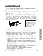
background image

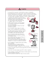
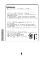
Consult with the customer concerning the location of installation.

Avoid places where fires could occurs, shch as those where gasoline
benzene and adhesives are handled, or places in which corrosive gases
(ammonia, chlorine, sulfur, ethylene compounds, acids) are present.
This may cause incomplete combustion or other component failure.

Locate the vent terminal so that there are no 
obstacles around the termination and so that
exhaust products cannot accumulate.
Do not enclose the vent termination with 
corrugated metal or other materials.

Install the water heater in area that allows 

for the proper clearances to combustible 
and noncombustibles.
Consult the installation manual for proper 

clearances required.

Do not install the water heater in a place 

where it may be damaged by falling objects.

The water heater must be installed in a place 

where supply and exhaust vent pipes can 

be installed as directed.(Internal model)

Do not install the water heater where the 
exhaust gas will vent onto walls or material 
not resistant to heat.

Do not vent directly onto trees & shrubs nor 
where animals may congregate.
The heat and moisture from the water heater 

may cause discoloration of walls and resinous 

materials, or corrosion of aluminum materials.

Avoid installation in places where dust or debris

will accumulate.
Dust may block the air-supply opening, 
causing the performance of the fan motor 

to drop and incomplete combustion to occur as result.

Install in a location where the exhaust gas flow will not be affected by fans
or range hoods.

Ensure that noise and exhaust gas will not affect neighbors.

Avoid installation in places where special chemical agents (e.g. hair spray 
or spray detergent) are used.
Ignition failures and malfunction may occur as a result.

Содержание SHW-13

Страница 1: ...apply 6 A notice of intention to install shell be lodged with the recelant Municipal Authority and local Gas Authority prior to installation 7 This appliance is not intended for use by persons includi...

Страница 2: ...piping 47 9 Water Piping 47 10 Application Diagrams 50 11 Electrical Wiring 51 12 Condensate Drain 53 13 Maintenance 54 14 Trial Operation 55 15 Dimensions 56 Servicing Manual 61 1 Servicing schedule...

Страница 3: ......

Страница 4: ...Supplier outdoor...

Страница 5: ...30cm 5cm 5cm 60cm 30cm Ground...

Страница 6: ......

Страница 7: ...1km Supplier 13 35 13...

Страница 8: ...External Main Unit SHW 13 33 Outdoor 57 58 Air Intake SHW 13 26 Model SHW 30 33 Model...

Страница 9: ...Indoor 59 60 SHW 30 33 Model SHW 13 26 Model Internal Main Unit SHW 13 33...

Страница 10: ...40 It indiates Priority mode is turned on for your safety Priority mode is used only when a secondary remote is installed...

Страница 11: ...ller to use priority function The Green priority light will glow indicating that this cont roller can controll the temperature and also the water he ater is ready to supply hot water If the controller...

Страница 12: ...40 37 50 55 60 65 70 37 50DegC in 1 increments 50 Hold UP 45 50 50 Hold it down for 5sec button down for...

Страница 13: ...external pipes from freezing Electrical heating elements are used for freeze protection 11...

Страница 14: ...External Model Internal Model...

Страница 15: ...1 1 liters Place a bucket under the unit and drain water from it for water leak Be careful not to lose the O Ring seal to relieve pressure...

Страница 16: ...2 5LPM 2 5lpm 240V 50Hz 15 15 12...

Страница 17: ...2 5 LPM 15 15 12...

Страница 18: ...1000kPa...

Страница 19: ......

Страница 20: ......

Страница 21: ...7MJ h 140 MJ h 50 20 R 1 2 15mm R 3 4 20mm 33 0 100 100 Temperature Storage Temperature Operating Temperature Controller 15 75 0 70 Thermal Efficiency Setting Automatic burner control system circuit V...

Страница 22: ...101 SHW 30 33 External Model 104 109 111 112 113 114 116 103 102 105 106 107 108 110 115...

Страница 23: ...115 116 SHW 30 33 Internal Model...

Страница 24: ...214 215 Burner Assembly SHW 30 33 Internal External...

Страница 25: ...326 325 327 328 329 Water Line Assembly SHW 30 33 Internal External...

Страница 26: ...9 2080538 Overheat thermostat 310 2070447 Sensible heat exchanger 311 2090895 Hot water outlet pipe 312 3130378 Hot water temperature sensor 313 2080571 Ceramic heater 314 3011119 Ceramic heater fixin...

Страница 27: ......

Страница 28: ...Internal model Conversion Kit Case Air Intake Connector Tapping screw 8ea Flue collar sealing packing Only for SHW 13 26 Flue collar Only for SHW 13 26 Only for SHW 13 26...

Страница 29: ...240V AC 50Hz Please remove all packing materials from the water heater cabinet before commencing the installation For Internal model...

Страница 30: ...DegC Avoid installation above gas ranges or stoves Avoid installation between the kitchen fan and stove If fumes or a large mount of steam take measures to prevent the fumes and steam from entering i...

Страница 31: ...falling objects The water heater must be installed in a place where supply and exhaust vent pipes can be installed as directed Internal model Do not install the water heater where the exhaust gas wil...

Страница 32: ......

Страница 33: ......

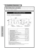
Страница 34: ...SHW 30 33 100 Abey s Twin Wall Flexible Gas Flue Kits SHW 13 26 75 Abey s Twin Wall Flexible Gas Flue Kits For the Internal model ABEY S TWIN WALL FLEXIBLE GAS FLUE must be used for both intake and fl...

Страница 35: ...25mm in 250mm 50cm 50cm 50cm Vent Terminal Internal Model...

Страница 36: ...Twin Wall Flexible Gas flue kit Maximum Vent Length 13 7 meters Equivalent Must be sealed by approved sealant INTERNAL MODEL 250mm 300mm Abey Twin Wall Gas Flex Abey sleeve used as a wall sleeve and t...

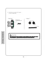
Страница 37: ...Vent Size 75 100 vent size 45 45cm Min 500mm Exhaust and Air intake terminals...

Страница 38: ...n accordance with the section of the latest edition of the AS NZ 5601 1 gas installations and any other statutory regulations 3 Insert the terminals to Exhaust and Air intake pipe Min 300mm Min 500mm...

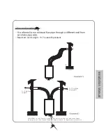
Страница 39: ...freezing air can enter into the vent and cause freeze damage to unit See Freeze Protection page in manual for appropriate precautions Maximum Vent Length 13 7 meters Equivalent 3 10 degree upward 3 10...

Страница 40: ...Air intake must be protected from any debris Sloping 25mm in 250mm 25mm in 300mm 100 SHW 30 33 75 SHW 13 26 Abey gas flex flue kit Abey gas flex flue kit Maximum Vent Length 13 7 meters Equivalent Mus...

Страница 41: ...25 250mm 25 300mm 25 250mm 25 300mm 1m 5m SHW Maximum total equivalent meters of vent pipe 13 7 meters Assemble the Abey gas flex sealant tape as shown in the diagram on the right 46...

Страница 42: ...When the gas connections are completed it is necessary to performa gas leak test either by applying soapy water to all gas fittings and observing for bubbles or by using a gas leak detection device A...

Страница 43: ...The pressure relief valve is required to be drained to Tundish and then piped at a suitable position outside the building to comply with AS 3500 and local by laws and regulations 48...

Страница 44: ...200kPa 96 to 482kPa 200kPa 49...

Страница 45: ...50...

Страница 46: ...le that can have the power supply interrupted by a switch that is used to control lights or another appliance If the supply cord is damaged it must be replaced by the service agent or similarly qualif...

Страница 47: ...SHW 30 33 Model 240VAC 5A AC 240V 52...

Страница 48: ...SHW 53...

Страница 49: ...We recommend that the maintenance schedule for the life expectancy of the appliance is every Twelve 12 months 54...

Страница 50: ...55...

Страница 51: ...125 4 729 20A 20A 20A 471 125 7 80 6 48 9 91 1 140 452 80 9 229 9 55 6 SHW 30 33 External Model Outlet 57...

Страница 52: ...123 8 11 1 152 4 12 7 730 3 700 20A 20A 20A 469 9 501 7 209 6 65 1 34 9 66 7 90 5 139 7 469 9 69 9 228 6 55 6 SHW 30 33 Internal Model...

Страница 53: ...but be sure to keep the length in the manufacturer recommendation Before Installing the multiful controllers make sure to turn the power off request The multiful controllers can be installed for a wat...

Страница 54: ...ck the maininjectorfor blockageor damage 6 Check that the flue terminalis unobstructed and than the fluesystemis sealed correctly The servicing procedures are covered more fully in Frames2 and MUST be...

Страница 55: ...ENT OF COMPONENTS Whenreplacing ANYcomponent 1 Isolate theelectricity supply 2 Turnoff the gassupply 3 Remove thefrontcase Afterreplacing ANYcomponent check operation of thewater heater including gass...

Страница 56: ...d water valve open close Cold water inlet Hot water outlet Gas 4 CLEANING THE COMBUSTION CHAMBER HEAT EXCHANGER AND BURNER 1 Refer to Frame 2 2 Remove the14 screws retaining the combustion chamber cas...

Страница 57: ...from the combustion chamber x 14 6 SPARK PLUG 1 Referto Frame 2 2 3 4 Remove the4 screws to separate the spark plug bracket fromthecombustion 5 6 Fit thenew components Reassemble in reverse order Chec...

Страница 58: ...ure sensor 7 IGNITOR REPLACEMENT 1 Refer to Frame 2 2 3 4 Remove the2 screws to separate the ignitor fromthefan 5 Fit thenew ignitor Reassemble in reverse order Check theoperation of thewater heater R...

Страница 59: ...9 FLOW RATE CONTROL VALVE REPLACEMENT 1 Refer to Frame 2 3 2 3 4 Remove the2 clips from T socket cold water to seprate the water control valve 5 6 Reassemble in reverse order Checktheoperation of thew...

Страница 60: ...of the water heater Refer to Frame2 Separate the overheat thermostat from the bracket REPLACEMENT 11 FAN REPLACEMENT 1 Referto Frame 2 7 ignitor replacement 2 3 4 Remove the2 screws to separate the f...

Страница 61: ...heoperation of thewater heater Referto Frame 2 3 Separate the duct assembly and latent heat exchanger Turn the nut of latent heat exchanger counter clockwise and then remove from the duct assembly the...

Страница 62: ...e manometer to the pressure port Turn on the gas supply Measure the gas pressure when water heater is operating 2 MEASURING THE MANIFOLDER GAS PRESSURE 1 2 3 4 5 Turn off the gas supply Loosen the scr...

Отзывы: