background image

22

English

Installation Instructions

Installing the Anti-Tip Bracket and Foot, cont.

Wall-Mounting the Anti-Tip Bracket

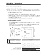
For this option to be suitable, the range front panel must be 26 1/2" (67.3 cm) or less from the wall, 

and the bracket screws must be able to engage the base plate inside the wall. Notches on the sides 

of the bracket indicate the minimum height of the base plate and that any floor covering thickness 

will not impede secure threading.
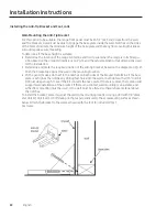
To determine if the base height is suitable:
• 

Determine the location of the range centerline and front panel when the range is in its final po

-

sition based on the product dimensions on Pg. 14 and the actual cabinet/cutout dimensions used 

for the installation.

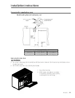
•  Determine and mark the required position of the anti-tip bracket, based on the diagram on Pg. 21. 

Push the bracket up against the wall in the mounting location.

•  With a pencil, make a dot next to the notches on both sides of the bracket. Determine if the base 

plate is as high as the notches by drilling test holes into the wall at both dots with a 1/16” drill bit. 

Drill just deep enough to see if the bit contacts the base plate. If there is contact, the location will 

support wall installation of the bracket. If there is no contact, wall mounting is unsuitable, and 

either floor mounting must be used, or the wall must be altered so there is base material above 

the notches.

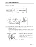
To install the bracket, place it against the wall in the mounting location. Using a drill with 1/8" diam-

eter drill bit, drill four (4) 1 5/8” deep pilot holes perpendicular to the screw seating surfaces shown 

below. Attach the bracket to the wall as shown with the four (4) included #12 x 1
¾ screws.

Содержание Modernist Series

Страница 1: ...Installation Instructions Modernist Pro Range DOP48M86D DOP36M86D Part No 115116 Rev A...

Страница 2: ...t is Included DOP48M86D 10 What is Included DOP36M86D 11 Needed Tools and Parts 12 Installation Requirements 13 Pre Installation Checklist 13 General Requirements 13 Location Requirements 16 Gas Requi...

Страница 3: ...ing codes and ordinances Leave this manual with the owner and write the unit s model serial s inside foreasy reference Installation of this appliance requires basic mechanical skills The ownershall se...

Страница 4: ...e of California to cause cancerand birth defects orother reproductive harm Gas appliances can cause low level exposure to Proposition 65 listed substances e g carbon monoxide formaldehyde soot caused...

Страница 5: ...ge shall be used only if the hood and range are designed and tested perthe Standard forDomestic Gas Ranges ANSI Z21 1 CSA1 1 and listed by an independent testing lab forcombination use Neveruse the ra...

Страница 6: ...se in a neutral orground circuit Use a dedicated 240 Vac 60 Hz 50 Amp breakerforthe 48 Range and a 40 Amp breakerforthe 36 Range A time delay fuse orcircuit breakershould be used Plug only the range i...

Страница 7: ...ral Gas and Propane Installation Code CAN CGA B149 1 orthe current Propane Installation Code CAN CGA B149 2 and with local codes where applicable This range has been design certified by UL according...

Страница 8: ...s next to the electrode Do not pourwaterorotherliquids into the cooktop Select cookware that is designed forcooktops and that covers the grate Burnerflames should stay fully underthe cookware Do not u...

Страница 9: ...the oven is not turned off and powerreturns the oven may begin to oper ate again Unattended food could catch fire orspoil Self Cleaning Safety During self cleaning the oven operates at about 800 F 42...

Страница 10: ...range comes with brass and porcelain burnercaps to suit customerpreference Grates 3 Burnerheads 6 and Burner caps 7 Glide racks 2 Convection filter 2 Temp Probe 1 Wire rack 1 Steam tray 2 Anti tip bra...

Страница 11: ...hat Is Included DOP36M86D The range comes with brass and porcelain burnercaps to suit customerpreference Grates 3 Burnerheads 6 and Burner caps 7 Glide racks 2 Convection filter 3 Temp Probe 2 Wire ra...

Страница 12: ...onnector in ID x 5 ft Flare union adapter in NPT x in ID 135 degree elbow op tional Lag bolt or1 2 in OD sleeve anchor Flare union adapter1 2 in NPT x1 2 in ID Flat blade screwdriver Phillips screwdri...

Страница 13: ...m from all adjacent surfaces The range complies with the maximum allowable wood cabinet temperature of194 F 90 C Ensure the adjacent wall covering countertops and cabinets can withstand such heat to a...

Страница 14: ...14 English Installation Requirements Product Dimensions Product tolerances 1 16 1 6 mm DOP36M86D 35 7 8 91 1 cm wide DOP48M86D 47 7 8 121 6 cm Range Installed Range Installed with Downdraft Vent...

Страница 15: ...mended Minimum Maximum 1 Vertical from range grate level to combustible overhead surface if installing an overhead hood see hood specifications forminimum required clearances 2 Cabinet countertop dept...

Страница 16: ...uirements DOP36M86D rear DOP36M86D rear 1 Measurement with appli ance legs adjusted to lowest height 2 The hole size forthe electri cal wiring may be increased to11 8 2 9 cm by removing the conduit br...

Страница 17: ...d on off Installation must allow access to the gas shut off valve when the unit is in stalled and access to the remote circuit breakerpanel fuse box without moving the range The gas supply piping and...

Страница 18: ...n the gas inlet and range forturning on off gas to the appliance Ensure the connectors are installed by a qualified installer To avoid leaks and personal injury neverinstall used connectors on a new p...

Страница 19: ...ician if you doubt that the outlet is properly grounded Do not alterthe powerplug Have a properoutlet installed by a qualified electrician All wiring grounding must complywith local codes or in theira...

Страница 20: ...table however if the range s front panel is over261 2 67 3 cm from the back wall orif the flooris too thick floormounting must be used Preparing forInstallation Floor Mounting the Anti Tip Bracket To...

Страница 21: ...hor holes then insert and tighten the screws Attaching the Bracket to a Wood Floor 1 Ceramic stone other hard flooring overwood Drill 4 countersink holes to access the wood for drilling pilot holes 2...

Страница 22: ...required position of the anti tip bracket based on the diagram on Pg 21 Push the bracket up against the wall in the mounting location With a pencil make a dot next to the notches on both sides of the...

Страница 23: ...P48M86DL C 14 1 8 35 9 cm 3 1 2 8 9 cm Removing the Oven Door Do not try to disengage the hinge catches with the door s removed The hinge springs could release caus ing personal injury Do not lift orc...

Страница 24: ...an electric range in new construction follow Steps 2 and 3 for 4 wire connection A 3 wire or4 wire single phase A C 240 Volt 60 hertz electrical system is required If the home electrical service does...

Страница 25: ...a 3 wire Conduit Aluminum building wire may be used but must be rated forthe correct amperage and voltage Connect wires according to Step 4 depending on the numberof wires Wire used location enclosur...

Страница 26: ...rews to 35 50 in lbs Any tightermay damage the wires Gas Connection Turn off the gas supplyvalve and turn off powerto the range at the circuit breakerorfuse box before con necting the gas line Do not...

Страница 27: ...e to the regulator 5 Turn off all cooktop controls then turn on the gas supply 6 With a soap and watersolution check all lines and con nections forleaks 7 Turn off the gas supplyvalve Final Installati...

Страница 28: ...til the notch on the bottom of each hinge slips overthe lowerlip of each hinge receptacle Wire connectorunderthe right side of the door should be connected 2 Lowerthe doorto the fully opened position...

Страница 29: ...g the knobs align the D shaped opening on the back of the knob with the end of the valve shaft Gently push the knob on until it stops Lifting the door hinge latches too much makes fasten ing the two s...

Страница 30: ...ile anotherburneris on 1 Orient the burner head so the electrode opening aligns with the electrode 2 Install the burner head so the electrode passes through its opening in the head Ensure the burner h...

Страница 31: ...es as shown at left The bottom of the head fits within the burner base 2 Turn the head until it drops into place Twist the head back and forth slightly to ensure it is properly seated 3 Put the burner...

Страница 32: ...h the tabs on the bottom of the ring to the slots on the head Twist each ring back and forth slightly to verify it is properly seated 3 Put the burner caps on the burner rings Use either the supplied...

Страница 33: ...of the right grate is notched to help orient the grates correctly See the graphic below To correctly position the grates 1 Find the notch on the back of the right hand grate and orient the grate prope...

Страница 34: ...lve Removing and Reinstalling the Range If the range does not operate properly 1 Verify that powerand gas are supplied to the range 2 Check the electrical connections and gas supply to verify properin...

Страница 35: ...tip bracket and foot as instructed Pgs 20 23 Was the gas supply inlet pressure measured to ensure it does not exceed the maximums stated in these instructions Pg 18 Is the range connected to the gas...

Страница 36: ...what purpose was the product purchased A Replacement only C New Home B Part of a Remodel D Other 4 What is yourhousehold income A Under 75 000 D 150 000 200 000 B 75 000 100 000 E 200 000 250 000 C 10...

Страница 37: ...RANTY PROCESSING DEPT PO BOX 90070 CITY OF INDUSTRY CA 91715 9907 NO POSTAGE NECESSARY IF MAILED IN THE UNITED STATES BUSINESS REPLY MAIL FIRST CLASS MAIL CITY OF INDUSTRY CA PERMIT NO 1600 POSTAGE WI...

Отзывы: