


ENGLISH
50
8.4
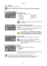
Optional configurations
Additional settings
This screen allows the activation or deactivation of the alarm buzzer that warns and accompanies any warning
and/or alarm phenomena occurring in the system.
8.5
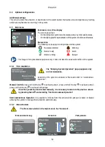
Main menu
Panoramic view of the display
The screen describes:
-
On the left pump 1 symbol and its status, pump 2 symbol and its status.
-
On the right a graphic representation of the system condition and its status.
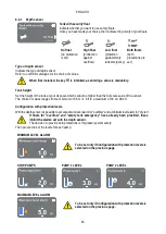
Status icons
The following icons apply to both pumps and the system
No status detected
Warning
Device ready
Alarm
Device running
Danger
The image is for representative purposes only. It does not describe an actual condition of the system.
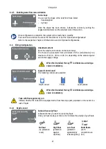
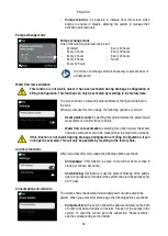
8.5.1
First installation
The “Pumping System Operation” pop-up appears only
on first installation.
Activation of the system is allowed via "Manual Control" or "Autonomous
Operation".
Manual Control: press and hold the key to activate pump 1, press and hold the key to activate pump 2,
press and hold the key to activate both pumps.
Once the system has been tested manually, it is necessary to return to the previous screen
by pressing the ke and selecting "Start Autonomous Operation”
Start Autonomous Operation: it is possible to indicate from this screen which pumps to enable or disable,
allowing the system to manage their activation autonomously.
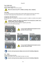
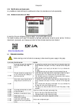
8.5.2
Menu structure
The first screen visible in the main menu is the “Overview”.
Error and Alarm Log
Overview
Pump status
Содержание NGPANEL
Страница 2: ...Pag 1 Pag 31 ITALIANO ENGLISH...


