ENGLISH
29
7.
PREPARATION OF THE ALARM SYSTEM FOR FEKAFOS 280 AND 280 DOUBLE
(Supplied only on request for Fekabox 200)
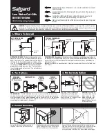
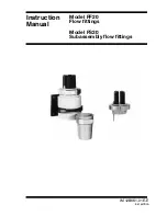
The preparation consists of having a float support composed of a PP pipe, fig. 15. For Fekabox 200 the length must be shortened to 184 mm.
Strictly respect the lengths shown in the figure.
Pass the float cable out of the tank, through the preassembled grommet
, tighten
the ring nut and connect it to the control unit. For Fekabox 200, in the kit supplied, along with
the alarm floating support there will be an extra cable clamp, necessary for the float cable to
come out.
Before filling the tank, activate the float manually to check the operation of the alarm system.
Make a test of the complete system with clean water, checking that the alarm system
intervenes only in the case of a pump malfunction or lack of power in the mains.
To do this, proceed as follows:
1.
Fill the tank up to pump intervention level and interrupt the power supply to the pump. In
this situation the alarm system must not intervene.
2.
Continue filling the tank until the alarm system intervenes. Check that in this condition the
water level is a few centimetres below the MAX emergency level 510 mm for Fekabox
200 and 680 mm for Fekafos 280 – 280 D.
If this condition does not occur, shorten the length of the cable between the cable grommet and the
safety float.
The maximum level alarm float system can be managed by panels of the ED, E2D, E-BOX
family and by the Control AS1. The latter is an electronic control unit with charge reserve
already equipped with a float. (Fig.16 – pag.153)
8.
FIRST START-UP
Before starting up the electropump check that in the tank system there is no residue or other material that could harm the
correct operation of the system.
In this phase you can leave the interception valve in the inlet pipe closed and fill the lifting station with clean water. Open the interception valve
in the delivery pipe and check that the pipes are tightened and perfectly sealed and that the electropump is working correctly. Check also that
the electropump is primed. Open the interception valve in the inlet pipe and check that the station is working correctly.
The flow of liquid coming from the various utilities must not prevent the correct operation of the floats present in the container.
In the case of a three-phase electropump, check that the impeller is turning in the correct direction. Check also the electropump manual. Check
that the levels of float intervention are correct, and if necessary adjust them to suit the actual needs of the system. When there are two
electropumps, the floats must be adjusted so that the second pump starts after the first and only if the first is not able to send to the sewer duct
as much liquid as arrives from the various utilities. Check that the electropump cannot become unprimed during operation. Check that the
number of starts per hour is compatible with the characteristics of the system components. Check that the system is working correctly and put it
into service. Close the cover or covers of the station, screwing them into place. If necessary, fix the cover in its seat in such a way as to prevent
unauthorised opening of the cover (see chapter 4.7).
8.1
Operating flow rate
It must be guaranteed that the speed of the liquid in the delivery pipe is at least 0.7 m/s and lower than 2.3 m/s.
8.2
Operation
When the liquid in the tank reaches the level corresponding to the closure of the float contact that commands the electropump, the pump starts
and gradually empties the container. The electropump stops when the liquid reaches the minimum level corresponding to the opening of the
float contact. When there are two electropumps, the floats must be adjusted so that the second pump starts after the first and only if the first is
not able to send to the sewer duct as much liquid as arrives from the various utilities. There may be a float placed higher than the others in the
pumping station, its function is to indicated the presence of an abnormally high level of the liquid in the tank.
9.
MAINTENANCE
After starting up the plant, it is advisable to inspect and clean it, especially the no return valve, about every three months. This interval may be
increased after the first inspections have given a favourable outcome.
Clean the pump accurately, removing any foreign bodies stuck in the intake grille and check that the float moves freely. If necessary, remove the
pump from the tank.
It is recommended to clean the system at least once a year with running water, operating the pump repeatedly.
Fig. 15
shorten the
pipe to
Fekabox
200
ALARM FLOAT
Содержание FEKABOX 200
Страница 4: ...ITALIANO 2 Fekabox 200 Fekafos 280 280 Double Fekafos 550 Double ...
Страница 14: ...FRANÇAIS 12 Uniquement pour Fekafos 280 Fekabox 200 Fekafos 280 280 Double Fekafos 550 Double ...
Страница 24: ...ENGLISH 22 Only for Fekafos 280 Fekabox 200 Fekafos 280 280 Double Fekafos 550 Double ...
Страница 34: ...DEUTSCH 32 Fekabox 200 Fekafos 280 280 Double Fekafos 550 Double Nur für ...
Страница 44: ...NEDERLANDS 42 Fekabox 200 Fekafos 280 280 Double Fekafos 550 Double Alleen voor ...
Страница 54: ...ESPAÑOL 52 Fekabox 200 Fekafos 280 280 Double Fekafos 550 Double Sólo para ...
Страница 64: ...РУССКИЙ 62 Fekabox 200 Fekafos 280 280 Double Fekafos 550 Double Только для ...
Страница 74: ...ČESKỲ JAZYK 72 Fekabox 200 Fekafos 280 280 Double Fekafos 550 Double Pouze pro ...
Страница 84: ...POLSKI 82 Fekabox 200 Fekafos 280 280 Double Fekafos 550 Double Tylko dla ...
Страница 94: ...ΕΛΛΗΝΙΚΑ 92 Fekabox 200 Fekafos 280 280 Double Fekafos 550 Double Μονάχα για ...
Страница 104: ...TÜRKÇE 102 Fekabox 200 Fekafos 280 280 Double Fekafos 550 Double Sadece için ...
Страница 114: ...УКРАЇНСЬКА 112 Fekabox 200 Fekafos 280 280 Double Fekafos 550 Double Тільки для моделі ...
Страница 124: ...ROMÂNĂ 122 Fekabox 200 Fekafos 280 280 Double Fekafos 550 Double Numai pentru ...
Страница 134: ...SRPSKI 132 Fekabox 200 Fekafos 280 280 Double Fekafos 550 Double Samo za ...
Страница 144: ...中文 142 Fekabox 200 Fekafos 280 280 Double Fekafos 550 Double 仅用于 双重 型号 ...
Страница 152: ...DRAWINGS 150 Fig 1 Fig 2 Fig 3 Fig 7a Fig 7b Fig 6 ...
Страница 153: ...DRAWINGS 151 FEKABOX 200 l Fig 8 FEKA VS Fig 9 FEKA 600 FEKA VX Fig 9 a Fig 9 b ...
Страница 155: ...DRAWINGS 153 Fig 16 ...