ENGLISH
-
13
GB
1.
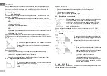
Unscrew the 4 screws fixing the motor assembly to the pump body (figure A).
2.
Rotate the motor assembly keeping it in the seat where it couples with the pump body (figure A-B).
3.
Once the head has been rotated into the desired position, tighten the 4 screws, always
proceeding in cross formation (figure C).
If the motor assembly has been removed from its seat, pay the greatest attention during assembly,
taking care to insert the impeller completely in the floating ring before tightening the retaining screws
(figure D). If it has been correctly assembled, the motor assembly rests completely on the pump body.
Incorrect assembly may damage the impeller, causing a typical rubbing noise
when the circulator starts.
The electronic control device must always remain in vertical position!
Ensure that the connecting cable of the pressure sensor never comes in contact
with the motor casing.
5.3.
Non-return valve
If the system is equipped with a non-return valve, ensure that the minimum pressure of the circulator is
always higher than the valve closing pressure.
6.
ELECTRICAL CONNECTIONS
The electrical connections must be made by expert, qualified personnel.
-
The circulator does not require any external motor protection.
-
Ensure that the supply voltage and frequency are the same as the values indicated on the
electrical data plate of the circulator.
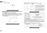
Reference
(Figure 4 and Figure 5)
Description
1
Pull-out terminal board for connection of the supply line:
1x220-240 V, 50/60 Hz
2
auxiliary LED
3
system live indicating LED
4
Connector for connecting twin circulators
5
Connector for connecting the fluid pressure and temperature sensor
(standard)
6
Pull-out 13-pole terminal board for connecting the inputs and the
MODBUS systems
7
Pull-out 6-pole terminal board for alarm signals and system status
6.1.
Collegamento di Alimentazione
Before supplying power to the circulator, ensure that the cover of the EVOPLUS control panel is
perfectly closed!
6.2.
Electrical connections of Inputs, Outputs and MODBUS
EVOPLUS circulators are equipped with digital and analogue inputs and digital outputs so as to be able
to realise interface solutions with more complex installations. For the installer it will be sufficient to wire
up the desired input and output contacts and to configure their functions as desired (see par. par. 8.2.1
par. 6.2.2 par. 6.2.3 and par. 6.2.4).
Table 1 Electrical connections
Figure 6: Pull-out terminal board for supply
Figure 5: Electrical connections (rear)
Figure 4: Electrical connections (front)
Содержание evoplus
Страница 97: ...92 GR 1 IEC 536 1 NEC 2 Kg m 1mm s 30 3 EVOPLUS EN 61800 3 C2 4 4 2 4 3 5 EVOPLUS 5 1 EVOPLUS 1 80 C 30...
Страница 98: ...93 GR 5 2 90 P 2 3 1 4 A 2 A B 3 4 C D 5 3 6 4 5 1 1x220 240 V 50 60 Hz 2 LED 3 LED 4 5 6 13 MODBUS 7 6 1 5 4...
Страница 167: ...162 RU 1 IEC 536 1 NEC 2 3 EVOPLUS EN 61800 3 2 4 4 1 4 2 4 3 5 EVOPLUS 5 1 EVOPLUS 1 80 C 30...
Страница 168: ...163 RU 5 2 90 IP 2 3 1 4 2 3 4 D 5 3 6 4 5 1 1x220 240 50 60 2 3 4 5 6 13 MODBUS 7 6 1 5 4...
Страница 198: ...193 BG 1 4 A 2 A B 3 4 C D 5 3 6 4 5 1x220 240 V 50 60 Hz 3 LED 4 LED 5 6 7 13 MODBUS 1 5 4...
Страница 217: ...212 UA 1 IEC 536 1 NEC 2 3 EVOPLUS EN 61800 3 2 4 4 2 4 3 5 EVOPLUS 5 1 EVOPLUS 1 80 C 30...
Страница 218: ...213 UA 5 2 90 IP 2 3 1 4 2 3 4 D 5 3 6 4 5 1 1x220 240 50 60 2 3 4 5 6 13 MODBUS 7 6 1 5 4...
Страница 226: ......
Страница 227: ......


