12
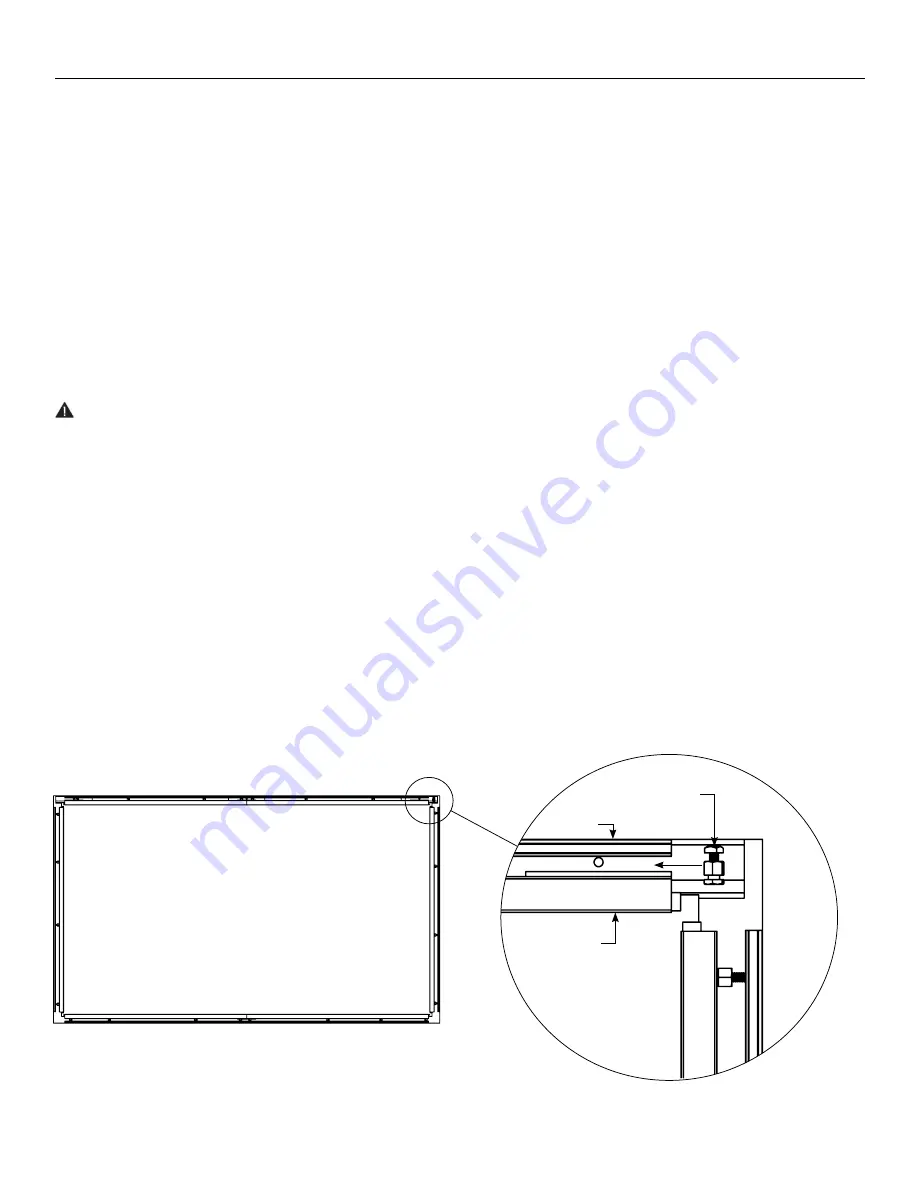
Figure 9
Installation (continued)
23. At the top section, align the T-track and the frame. Insert eight
tensioning assemblies (O) (four per frame section for larger
screens). Align the tensioning assemblies (O) so that they are
evenly spaced across the length of T-track and frame (See
Figure 9)
24. Tighten a minimum of two tensioning assemblies (O) per
frame section between the T-track and frame using a 1/2”
wrench. After two or three turns on one tensioning assembly,
move to another in order to prevent the bolts and nuts from
binding. Keep using this alternating method until at least two
(or more) tensioning assemblies, per frame section, have
secured the frame to the T-track on the top section of the
screen assembly. As the tensioning assemblies are tightened
the screen frame will pull gradually closer to the T-track. Do
not tighten fully at this time.
CAUTION: Do not proceed to next steps until a minimum
of two tensioning assemblies (O) per frame section are
attached fully and are holding the screen weight on the
top side.
25. Remove the three lifting brackets (D) from the wall opening
behind the T-track by loosening and removing the 1/4” x 1” lag
screws. The three ropes (N) should also be removed at this
time.
NOTE:
Once the lifting brackets have been removed, the
screen assembly will be held in place by the previously
attached tensioning assemblies.
26. Tighten all tensioning assemblies (O) on the top section of
the screen assembly until all eight (four per frame section)
are evenly spaced and secure on the top side.
NOTE:
Use the alternating method of two to three turns on
one assembly then moving to another assembly to prevent
the bolts and nuts from binding.
27. At the bottom section, align the T-track and the frame. Insert
eight tensioning assemblies (O) (four per frame section for
larger screens). Align the tensioning assemblies (O) so that
they are evenly spaced across the length of T-track and
frame.
28. Begin tightening the tensioning (O) assemblies between the
T-track and frame using a 1/2” wrench. After two or three turns
on one tensioning assembly, move to another in order to
prevent the bolts and nuts from binding. Keep using this
alternating method until the tensioning assemblies have
secured the frame to the T-track.
NOTE:
These tensioning assemblies (O) do not need to be
tightened down completely (no threads showing) because
the top frame is already anchoring the screen in place. The
bottom needs to be secure enough to the installer’s
discretion.
29. Repeat Steps 27 and 28 for the left and right sides of the
frame, using four tensioning assemblies (O) per frame
section.
Tensioning Assembly
Frame Section
T-Track


