xStack
®
DGS-3200 Series Layer 2 Gigabit Ethernet Managed Switch
22
Wall Installation Steps
Before beginning installation, simulate hanging the Switch by holding it against the wall with the wall mounting ears and marking
the positions of the oval holes. These holes will be used with the wall mounting ears for installing the concrete sleeve anchors.
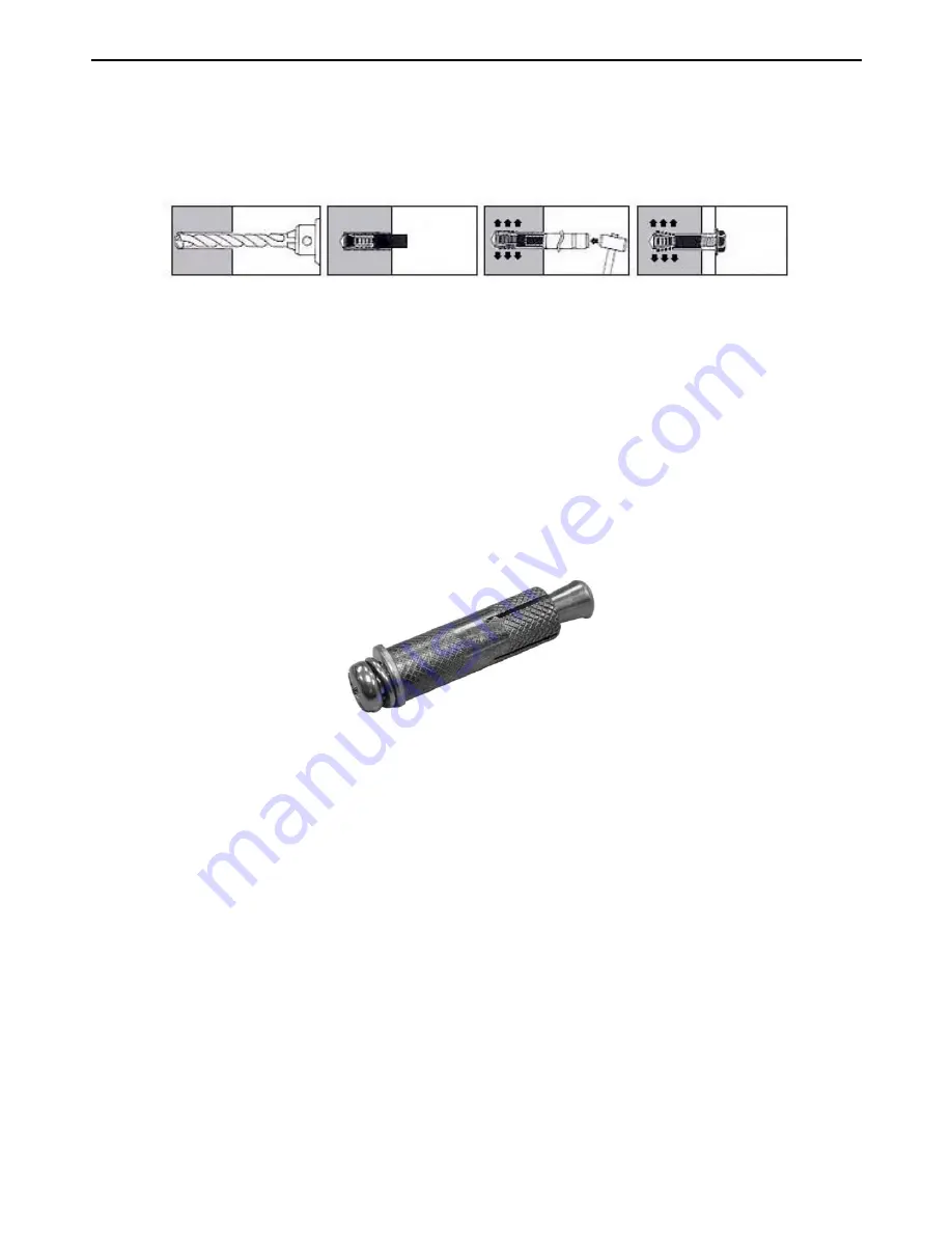
Figure 2- 9. Illustration of each installation step
1.
Use a power drill with an 11mm diameter bit to drill four holes at the marked points, each of a depth of 37 to 40
mm.
2.
For each hole, put the smaller end of one concrete sleeve anchor into the hole.
3.
Use a hammer to firmly smack each concrete sleeve anchor into one of the four holes. Each sleeve anchor
should be nearly flush with the wall the Switch is being mounted to.
4.
Complete the installation by firmly tightening each screw.
If the Switch is being mounted on a cement wall, D-Link recommends using a concrete sleeve anchor, such as the one depicted
below that is part of the optional D-Link Wall Mount kit, DRE-KIT018. The D-Link Wall Mount kit consists of 8 screws, 4
concrete sleeve anchors, and 2 wall ears.
Figure 2- 10. Concrete sleeve anchor
Power On
1.
Plug one end of the AC power cord into the power connector of the Switch and the other end into the local
power source outlet.
2.
After powering on the Switch, the LED indicators will momentarily blink green. This blinking of the LED
indicators represents a reset of the system.
Power Failure
As a precaution, in the event of a power failure, unplug the Switch. When power is resumed, plug the Switch back in.
Содержание xStack DGS-3200 Series
Страница 77: ...International Offices ...
Страница 79: ......


