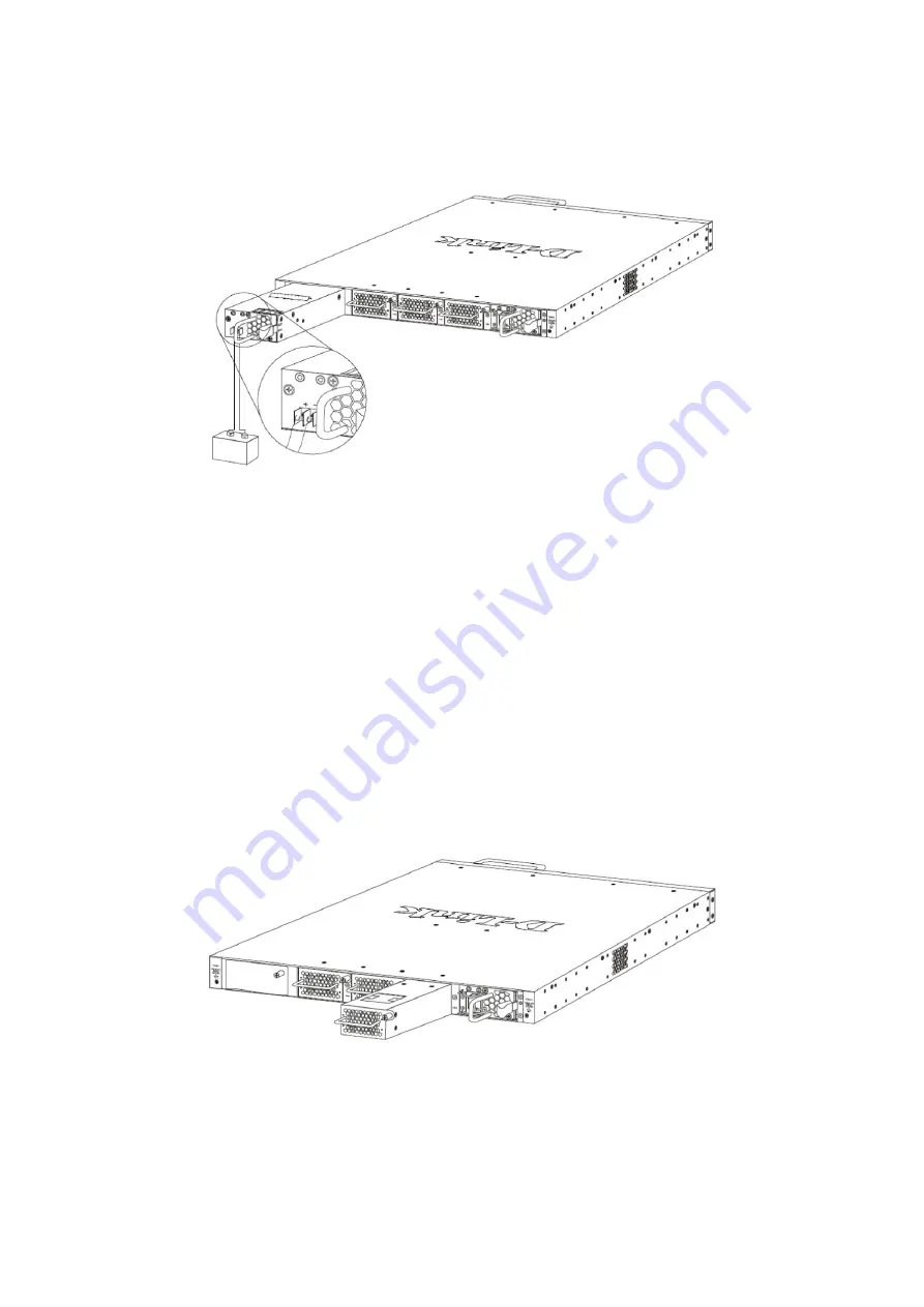
2. Connect the one end of the DC power cord supplied to a DC power module, that will be activated when
the AC power is not working, and to a power source (-48VDC/5.2A). Please make sure that connection
polarity (positive and negative) is correct.
The DC power and AC power of the device will back up each other immediately when one of the power
sources fail. If both power sources fail, unplug the switch. When the power source has been restored, plug
the switch’s power back in.
NOTE:
The Power Modules all support a specific airflow direction. This air-flow direction must be the same
as the Fan Module installed. By default the airflow direction of the Power Module and Fan Module installed is
front-to-back.
Installing Fan Modules into the Fan Module Ports
Located on the rear panel of this switch there are three fan module ports.
The user can easily remove and insert fan modules into these ports.
8
Содержание DXS-3600-32S
Страница 18: ...DXS PWR300AC 300 DXS PWR300DC 300 DXS 3600 FAN FB 19 18...
Страница 19: ...1 2 3 4 SFP 19...
Страница 20: ...100 240 50 60 1 18 AWG 20...
Страница 21: ...2 DC 48 5 2 21...
Страница 22: ...10 100 1000 RJ 45 VoIP UTP STP Link Act SFP SFP WDM QSFP DXS 3600 EM 4QXS 22...
Страница 24: ...DXS 3600 EM 4QXS QSFP DXS 3600 EM 4QXS DXS 3600 EM 4QXS 24...
Страница 27: ...Web CLI 27...
Страница 29: ...29...


