3
Restart Your Computer
Connecting Additional Computers
To The DI-634M
When you have completed the steps in this
Quick Installation Guide,
your connected
network should look similar to this:
Using additional Ethernet (CAT5 UTP) cables, connect your Ethernet-equipped computers
to the remaining Ethernet LAN ports on the back panel of the DI-634M.
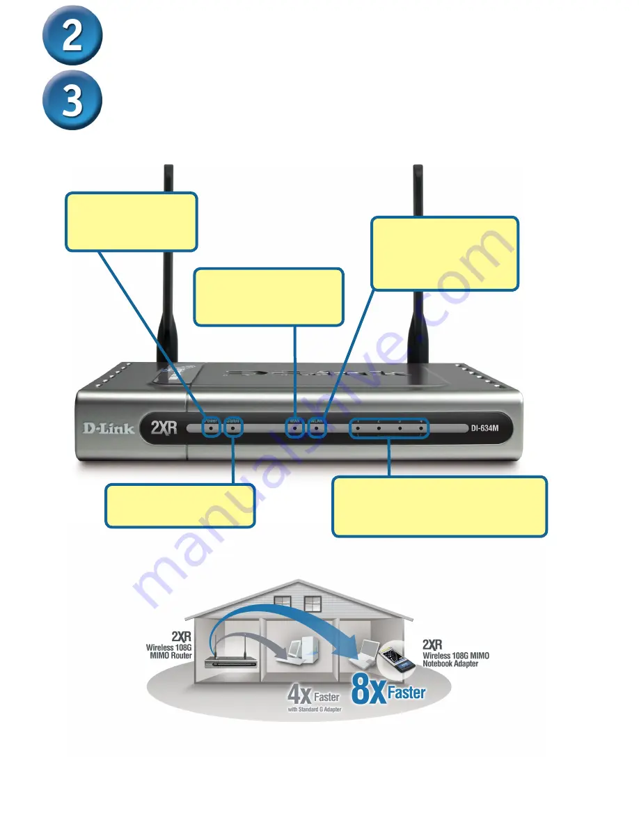
LOCAL NETWORK LEDs
– a solid light
on the port indicates a connection to an
Ethernet enabled computer on ports 1-4.
This LED blinks during data transmission.
Power LED
– a solid
light indicates a proper
connection to the power
supply.
WLAN LED
– a solid light
indicates that the wireless
segment is ready. This LED
blinks during wireless data
transmission.
Status LED
– a blinking light
indicates that the DI-624 is
functioning properly.
WAN LED
– a solid light
indicates connection on the
WAN port. This LED blinks
during data transmission.
* Maximum wireless signal rate derived from IEEE Standard 802.11g specifications. Actual data throughput
will vary. Network conditions and environmental factors, including volume of network traffic, building materials
and construction, and network overhead lower actual data throughput rate.


