


Solid amber
When there is a secure 100/1000 Mbps connection at the
port.
Blinking amber
When there is reception or transmission occuring at the port.
Light off
No link.
Link/Activity/Speed
(per 10GBase-X SFP+
port)
Solid green
When there is a secure 10 Gbps connection at the port.
Blinking green
When there is reception or transmission occuring at the port.
Solid amber
When there is a secure 1000 Mbps connection at the port.
Blinking amber
When there is reception or transmission occuring at the port.
Light off
No link.
PoE Status
(per 10/100/1000Base-T
port in PoE mode)
Solid green
PD device insert and power feeding.
Solid yellow
PD device insert but failur occurs.
PSE can't provide power to PD due to PD error or power
budget is not enough.
Light off
No PD device insert.
Installation Guidelines
This section will discuss the hardware installation guidelines that the user must follow in
order to properly and safely install this switch into the appropriate environment.
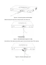
Visually inspect the power cord and see that it is fully secured to both the power
connector, on the Switch, and the electrical outlet that supplies power.
Install the Switch in a fairly cool and dry place within the acceptable operating
temperature and humidity ranges.
Install the Switch in a site free from strong electromagnetic field generators such as
motors, vibration, dust, and direct exposure to sunlight.
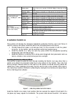
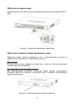
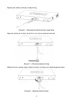
Installing the Switch without a Rack
This section is used to guide the user through installing the Switch in an area other than a
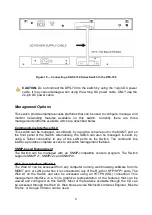
switch rack. Attach the included rubber feet to the bottom of the Switch. Take note that
there should be marked blocks on the bottom of the Switch to indicate where to attach the
rubber feet. These markings are usually found in each corner on the bottom of the device.
The rubber feet cushion the Switch, protecting the casing from scratches and preventing it
from scratching other surfaces.
Figure 1 — Attaching rubber feet to the Switch
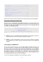
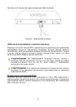
Install the Switch on a sturdy, level surface that can support the weight of the Switch. Do
not place any heavy objects on the Switch. The power outlet should be within 1.82 meters
3
Содержание DGS-3130-30PS
Страница 15: ...1 1 82 10 19 2 3 15...
Страница 16: ...DGS 3130 30PS SFP SFP 4 5 16...
Страница 17: ...6 7 8 17...
Страница 18: ...9 RPS 15 DPS 700 DPS 700 RPS 22 RPS 18...
Страница 20: ...RJ 45 RS 232 RS 232 RJ 45 1 RS 232 2 RJ 45 COM1 COM2 115200 8 1 11 COM 20...


