background image

Introduction

This Quick Installation Guide gives instructions for setting up the D-Link DGS-3000-28SC switch. The
model you have purchased may appear slightly different from those shown in the illustrations.

Package Contents

Open the shipping carton of the Switch and carefully unpack its contents. Please consult the packing list
located to make sure all items are present and undamaged.
• One DGS-3000-28SC Switch
• AC power cord(s)
• One DC power source connector
• One RJ-45 to RS-232 console cable
• One set of Power Cord Retainer
• 2 Mounting Brackets
• Mounting kit
• Four rubber feet with adhesive backing
• One Quick Installation Guide
• Warranty Certificate
If any of the above items are damaged or missing, please contact your local reseller for replacement.
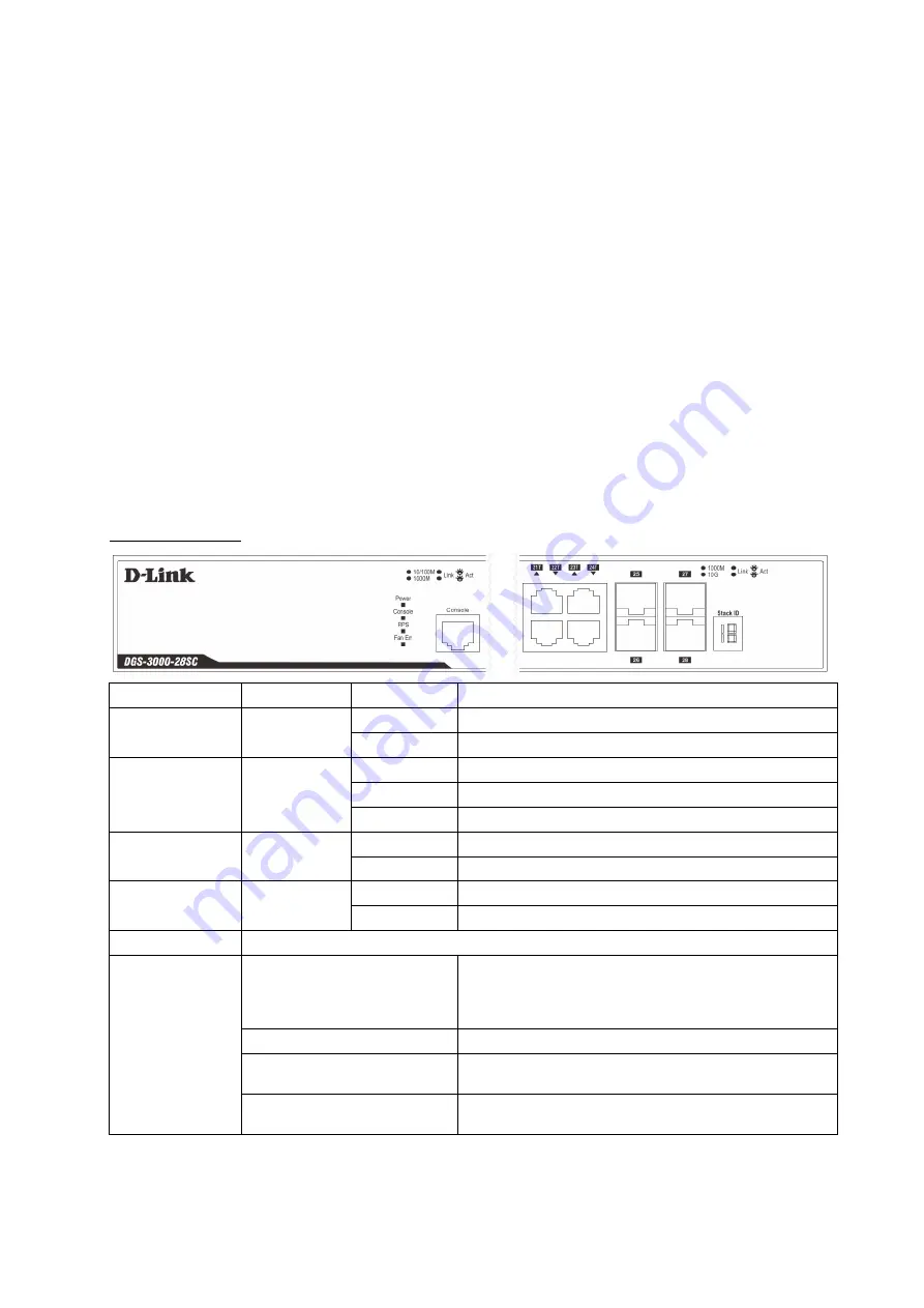
Hardware Overview

LED Indicators

LED

Colour

Status

Description

Power

Green

Solid Green

Power on.

Light Off

Power off.

Console

Green

Blinking Green During the Power-On Self Test (POST).

Light Off

The Power-On Self Test (POST) is finished.

Solid Green

A user is logged in through the console port.

RPS

Green

Solid Green

RPS is connected.

Light Off

RPS is not connected / RPS switch is turned off.

Fan Err

Red

Blinking Red

Any of the fans has failed.

Light Off

All fans are working normally.

Link/Act LEDs

The Switch has LED indicators for Link and Activity.

Stacking ID

1-6

For standalone Switches, this will display number “1”. For 
stacked Switches, this indicates the position in the stacking 
box ID, which can be assigned manually by the user or 
automatically by the system.

H

Indicates this switch is the master switch in the stack.

h

Indicates this switch is the backup master switch in the 
stack.

G

Indicates the Safeguard engine entered the exhausted 
mode.

2

Содержание DGS-3000-28SC

Страница 1: ...00 28SC 20 port 100 1000Base X SFP 4 port 100 1000Base T SFP combo and 4 port 10GBase X SFP Stackable Managed L2 Switch L2 20 100 1000Base X SFP 4 100 1000Base T SFP 4 10GBase X SFP Quick Installation...

Страница 2: ...nt Hardware Overview LED Indicators LED Colour Status Description Power Green Solid Green Power on Light Off Power off Console Green Blinking Green During the Power On Self Test POST Light Off The Pow...

Страница 3: ...e device s base Allow enough ventilation space between the device and the objects around it Installing the Switch in a Standard 19 Rack The Switch can be mounted in a standard 19 1U rack using the pro...

Страница 4: ...ower Power On AC Power Plug one end of the AC power cord into the power socket of the Switch and the other end into the local power source outlet Power Failure AC Power For AC power supply units as a...

Страница 5: ...AC power cord into the power socket of the Switch C Slide the Retainer through the Tie Wrap until the end of the cord D Circle the tie of the Retainer around the power cord and into the locker of the...

Страница 6: ...gher or equal to 2 5A Voltage protection must be apllied when the voltage is higher or equal to 15V Current protection must be apllied when the current is higher or equal to 6A 1 Make sure that the ON...

Страница 7: ...h 3 Using a standard AC power cord connect the RPS to the main AC power source A green LED on the front panel of RPS will illuminate to indicate a successful connection 4 Make sure that the ON OFF tog...

Страница 8: ...h Ethernet port will light green or amber when the link is valid Switch to Another Switch The Switch can be used to connect to any other switch or hub in the network This network topology is used when...

Страница 9: ...le or Category 5e copper cable depending on the type of port A valid connection is indicated when the Link LED is lit Management Options Web based Management Interface After successfully installing th...

Страница 10: ...s 8 Parity none Stop bits 1 Flow control none Under Properties select VT100 for Emulation mode Select Terminal keys for Function Arrow and Ctrl keys Make sure to use Terminal keys not Windows keys are...

Страница 11: ...s seen below As there is no default User name or Password click OK to proceed This will open the Web based user interface Additional Information For more detailed information on how to set up and conf...

Страница 12: ...5 c 2 6 7 2012 D 2013 E 2014 F 2015 G 2016 H 2017 I 2018 J 2019 0 2020 1 2021 1 2 9 A B D Link...

Страница 13: ...DGS 3000 28SC DGS 3000 28SC AC DC RJ 45 RS 232 2 19 4 Power Console Power On Self Test POST Power On Self Test POST RPS Fan Err Link Act 13...

Страница 14: ...Stacking ID 1 6 Stacking ID 1 H master h backup master G Safeguard engine exhausted mode 19 14...

Страница 15: ...SFP WDM SFP SFP 220 15...

Страница 16: ...C 16...

Страница 17: ...D E 11 4 12 6 2 5 A 15 6 17...

Страница 18: ...S 200A DPS 500A DPS 500DC RPS DPS CB150 2PS DGS 3000 28SC 1 2 14 DPS 200A DPS 500A DPS 500DC RPS 3 DPS 200A DPS 500A DPS 500DC DPS 200A DPS 500A DPS 500DC 4 5 DPS 800 1U 19 1 DPS 200A DPS 500A DPS 500...

Страница 19: ...2 DPS 800 RJ 45 10 100 1000 UTP STP 1000Base T 10 UTP STP Cat 3 4 5 100 UTP STP Cat 5 1 UTP STP Cat 5e 19...

Страница 20: ...SFP SFP SFP WDM SFP SFP RJ 45 SFP 1000 Cat 5e Web Web Microsoft Internet Explorer 5 5 Netscape 8 Mozilla Firefox 2 0 Safari 4 0 Google Chrome 6 0 20...

Страница 21: ...terminal Putty Minicom DB 9 RJ 45 1 DB 9 RS 232 2 RJ 45 Serial port COM 1 COM 2 Baud rate 115200 Data bits 8 Parity Stop bits 1 Flow control Properties VT 100 Ctrl Windows 3 Enter admin Web Web IP Ent...

Страница 22: ...Web User name Password Web http www dlink ru 22...

Страница 23: ...5 RPS Power Console RPS Fan Err Link Act Stacking ID 128 64 95 24 Mpps MAC 16K DRAM CPU 256 1 5 Flash 32 Jumbo 13 x x 440 x 209 9 x 44 2 156 100 240 50 60 56 2 118 69 MTBF 567884 3 49 5 Smart Fan Ethe...

Страница 24: ...24...

Отзывы: