background image

iv


TABLE OF CONTENT 

About This Manual ............................................................................... i


Purpose ............................................................................................ 1


Terms/Usage .................................................................................... 1


Introduction.......................................................................................... 2


Gigabit Ethernet Technology ........................................................... 2


Fast Ethernet Technology ................................................................ 3


Switching Technology ..................................................................... 3


VLAN (Virtual Local Area Network).............................................. 4


Features............................................................................................ 4


Unpacking and Installation .................................................................. 6


Unpacking........................................................................................ 6


Installation ....................................................................................... 6


Rack Mounting ................................................................................ 7


Connecting Network Cable.............................................................. 8


AC Power......................................................................................... 8


Identifying External Components ........................................................ 9


Front Panel....................................................................................... 9


Rear Panel ...................................................................................... 10


Understanding LED Indicators .......................................................... 11


Power and System LEDs ............................................................... 11


Ports 1~48 Status LEDs ................................................................. 11


mini-GBIC Port 45F ~ 48F LEDs.................................................. 12


Configuration ..................................................................................... 13


Installing the Web Management Utility ......................................... 13


Discovery List................................................................................ 14


Monitor List ................................................................................... 14


Device Setting................................................................................ 16


Содержание DGS-1248T - Switch

Страница 1: ... DGS 1248T WebSmart 48 Port 10 100 1000Mbps 4 Combo SFP Mini GBIC Gigabit Switch Manual First Edition Building Networks for People RECYCLABLE Information in this document is subject to change without notice i ...

Страница 2: ...equipment has been tested and found to comply with the limits for a Class A digital device pursuant to Part 15 of the FCC Rules These limits are designed to provide reasonable protection against harmful interference when the equipment is operated in a commercial environment This equipment generates uses and can radiate radio frequency energy and if not installed and used in accordance with this us...

Страница 3: ...yo case puede requerirse al usuario para que adopte las medidas adecuadas Attention Ceci est un produit de classe A Dans un environnement domestique ce produit pourrait causer des interférences radio auquel cas l utilisateur devrait prendre les mesures adéquates Attenzione Il presente prodotto appartiene alla classe A Se utilizzato in ambiente domestico il prodotto può causare interferenze radio n...

Страница 4: ...es 4 Unpacking and Installation 6 Unpacking 6 Installation 6 Rack Mounting 7 Connecting Network Cable 8 AC Power 8 Identifying External Components 9 Front Panel 9 Rear Panel 10 Understanding LED Indicators 11 Power and System LEDs 11 Ports 1 48 Status LEDs 11 mini GBIC Port 45F 48F LEDs 12 Configuration 13 Installing the Web Management Utility 13 Discovery List 14 Monitor List 14 Device Setting 16...

Страница 5: ...u 20 Configuring Setup Setting 21 Port Settings 21 VLAN Settings Virtual Local Area Network 23 Trunk Setting 25 Mirror Setting 27 Device Status 27 Statistics 28 System Setting 31 Trap Setting 31 Password Setting 32 Backup Setting 32 Reset Setting 33 Logout 33 ...

Страница 6: ...ernet 100Mbps Fast Ethernet and 10Mbps Ethernet network capabilities in a highly flexible package Purpose This manual discusses how to install your 48 Port 10 100 1000Mbps Gigabit Web Smart Switch Terms Usage In this manual the term Switch first letter upper case refers to your Web Smart Switch and switch first letter lower case refers to other Ethernet switches ...

Страница 7: ...d more users use applications that generate more traffic Upgrading key components such as your backbone and servers to Gigabit Ethernet can greatly improve network response times as well as significantly speed up the traffic between your subnets Gigabit Ethernet enables fast optical fiber connections to support video conferencing complex imaging and similar data intensive applications Likewise sin...

Страница 8: ... 10Mbps Ethernet environments it provides a straightforward upgrade and takes advantage of the existing investment in hardware software and personnel training Switching Technology Another approach to pushing beyond the limits of Ethernet technology is the development of switching technology A switch bridges Ethernet packets at the MAC address level of the Ethernet protocol transmitting among conne...

Страница 9: ...y and need for routers using faster switching instead Other VLAN utility includes Security Security is increased with the reduction of opportunity in eavesdropping on a broadcast network because data will be switched to only those confidential users within the VLAN Cost Reduction VLANs can be used to create multiple broadcast domains thus eliminating the need of expensive routers Features 48 10 10...

Страница 10: ...per device self learning and table aging 1632KBytes packet buffer Supports IEEE 802 3x flow control for full duplex mode ports Supports 802 1Q VLAN Supports Port base QoS 802 1p QoS Supports Trunk Supports Port mirroring Supports Port setting for Speed Disable Flow control Easy configuration via Web Browser Easy setting via Web Management Utility Standard 19 Rack mount size ...

Страница 11: ...ged please contact your local reseller for replacement Installation The site where you install the hub stack may greatly affect its performance When installing consider the following pointers Install the Switch in a fairly cool and dry place See Technical Specifications for the acceptable temperature and humidity operating ranges Install the Switch in a site free from strong electromagnetic field ...

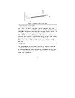
Страница 12: ... pads to the bottom Rack Mounting The Switch can be mounted in an EIA standard size 19 inch rack which can be placed in a wiring closet with other equipment Attach the mounting brackets at the Switch s front panel one on each side and secure them with the provided screws Figure 2 Combine the Switch with the provided screws Then use screws provided with the equipment rack to mount each Switch in th...

Страница 13: ... Switch can auto transform to MDI II or MDI X type so you can just make an easy connection that without worrying if you are using a standard or crossover RJ45 cable There are 4 additional SFP mini GBIC slots for optional SFP mini GBIC modules AC Power The Switch uses the AC power supply 100 240V AC 50 60 Hz The power switch is located at the rear of the unit adjacent to the AC power connector and ...

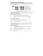
Страница 14: ...ir Ports Port 1 48 The DGS 1248T is equipped with fourty eight Gigabit twisted pair ports that are auto negotiable 10 100 1000Mbps and also support auto MDI MDIX crossover detection These ports can operate in half and full duplex modes SFP Mini GBIC Ports Option Port 45 48 The Switch is equipped with Four SFP Mini GBIC ports supporting optional 1000BASE X SFP Mini GBIC transceivers Note When the p...

Страница 15: ...Power Connector This is a three pronged connector that supports the power cord Plug in the female connector of the provided power cord into this connector and the male into a power outlet Supported input voltages range from 100 240V AC at 50 60Hz 10 ...

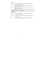
Страница 16: ... power Off When the Power turns off or the power cord has an improper connection CPU Management Indicator Blinking When the CPU is working the CPU LED is blinking On Off The CPU is not working Ports 1 48 Status LEDs Link ACT Link Activity On When the Link ACT LED lights on the respective port is successfully connected to an Ethernet network Blinking When the Link ACT LED is blinking the port is tr...

Страница 17: ...ast Ethernet network Off When the Speed LED lights off the respective port is connected to a 10Mbps Fast Ethernet network mini GBIC Port 45F 48F LEDs Link ACT On When the mini GBIC module is installed and connected to a network the Link LED lights on Blinking When the LED is blinking the port is transmitting or receiving data on the network Off No mini GBIC module is installed or connected to a ne...

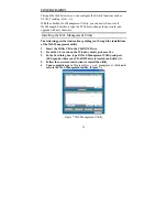
Страница 18: ...ing provides instructions guiding you through the installations of the Web Management utility 1 Insert the Utility CD in the CD ROM Drive 2 From the Start menu on the Windows desktop choose Run 3 In the Run dialog box type D Web Management Utility setup exe D depends where your CD ROM drive is located and click OK 4 Follow the on screen instructions to install the utility 5 Upon completion go to P...

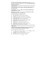
Страница 19: ...ddress IP Address Shows the current IP address of the device Protocol version Shows the version of the Utility protocol Product Name Shows the device product name System Name Shows the appointed device system name Location Shows where the device is located Trap IP Shows the IP where the Trap is to be sent Subnet Mask Shows the Subnet Mask set of the device Gateway Shows the Gateway set of the devi...

Страница 20: ...tor behind the View Trap button When the light is green it means that there is no trap transmitted and when it is red it means that there is new trap transmitted reminding us to view the trap Figure 8 Figure 8 When the View Trap button is clicked a Trap Information window will pop up It will display the trap information including the Symbol Time Device IP and the Event occurred Figure 9 The symbol...

Страница 21: ...Location Select the device in the Discovery list or Monitor List and press this button then the Configuration Setting window will pop up Figure 10 After filling in the data that you want to change you must fill in the password and press the Set button to process the data change immediately The default password of this 48 Port 10 100 1000Mbps Gigabit Ethernet Web Smart Switch configuration is admin...

Страница 22: ...e device in the Monitor List or select a device in the Monitor List and press the Web Access button to access the device in Web browser Toolbar The toolbar in the Web Management Utility has four main tabs File View Options and Help In the File TAB there is Monitor Save Monitor Save As Monitor Load and Exit Monitor Save To record the settings of the Monitor List to the default 17 ...

Страница 23: ... you to refresh the time for monitoring the device Choose 15 secs 30 secs 1 min 2 min and 5 min to select the time for monitoring In the Help TAB there is About function it will show out the version of the Web Management Utility Configuring the Switch The Web Smart 48 Port 10 100 1000Mbps Gigabit Switch has a Web GUI interface for smart switch configuration The Switch can be configured through the...

Страница 24: ... mask is 255 255 255 0 Open Internet Explorer 5 0 or above Web browser Enter the IP address http 192 168 0 1 the factory default IP address setting into the address location Figure 13 Or through the Web Management Utility you do not need to remember the IP Address Select the device shown in the Monitor List of the Web Management Utility to settle the device on the Web Browser When the following di...

Страница 25: ...page appears find the Setup menu on the left side of the screen Figure 16 Click on the setup item that you want to configure There are eleven options Port Settings VLAN Settings Trunk Setting Mirror Setting Device Status Statistics System Settings Trap Setting Password Setting Backup Setting and Reset Setting as shown in the Main Menu screen 20 ...

Страница 26: ...Settings menu Figure 17 this page will display each port s status Press the ID parameter to set each port s Speed Flow Control QoS priority and Link Status When you need to renew the posted information press the Refresh button The Link Status in the screen will display the connection speed and duplex mode otherwise this dialog box will display down when the port is disconnected 21 ...

Страница 27: ...he priority of Gigabit Fiber port is higher than Copper To change the port setting click on the ID parameter to enter the selected port to configure its Speed Disable Flow control and QoS setting Figure 18 Speed Disable This setting has six modes 100M Full 100M Half 10M Full 10M Half Auto and Disable for speed or port disable selections 22 ...

Страница 28: ...rtual Local Area Network A VLAN is a collection of switch ports that make up a single broadcast domain You can configure a VLAN for a single switch or for multiple switches When you create a VLAN you can control traffic flow and ease the administration of moves adds and changes on the network by eliminating the need to change physical cabling On VLAN settings there are two main settings VID Table ...

Страница 29: ...Figure 18 Port VID Setting When you select Port VLAN setting fill in each port s PVID value between 1 and 4094 Figure 19 24 ...

Страница 30: ...on data packets Figure 20 Trunk Setting The Trunk function enables the Switch to cascade two or more devices with larger bandwidths There are ten Trunking groups to be set and there are default ports in each member Click Enable to use the trunk function select the ports in each member to be trunk and click Apply to activate the selected trunk group 25 ...

Страница 31: ...Figure 21 Trunk Settings Be sure that the selected trunk setting port is connected to the device with a same VLAN group 26 ...

Страница 32: ...l be sent The selections of the sniffer mode are as follows TX transmit mode This mode will duplicate the data transmitted from the source port and forward it to the sniffer port RX receive mode This mode will duplicate the data sent to the source and forward it to the sniffer port Both transmit and receive mode This mode will duplicate both the data transmitted from and data sent to the source po...

Страница 33: ...Press Refresh when you need to renew the posted information Figure 23 Statistics The Statistics Menu screen will show the status of each port packet count 28 ...

Страница 34: ...Figure 24 Statistics For detailed packet information click on the ID parameter as in Figure 25 29 ...

Страница 35: ...Figure 25 30 ...

Страница 36: ...ogin Timeout is to set the idle time out for security issues When there is no action in running the Web Smart Utility and it times out you must re login to Web Smart Utility before you set the Utility Fill in the IP Address Subnet Mask and Gateway for the device Figure 26 Trap Setting The Trap Setting enables the device to monitor the Trap through the Web Management Utility Set the Trap IP Address...

Страница 37: ... the manager to secure the Web Management Switch You can use this function to change the password If you forget the password press the Reset button in the rear panel of the Switch The current setting includes VLAN Port Setting etc will be lost and the Switch will be restored to the default setting Figure 28 Set Password Backup Setting The backup tools help you to backup the current setting of the ...

Страница 38: ... the current password will not be erased Reset Setting The Factory Reset button helps you to reset the device back to the default setting from the factory Be aware that the entire configuration will be reset the IP address of the device will be set to the default setting of 192 168 0 1 Figure 30 Reset Setting Logout When you select this function the Web configuration will log out and return to fir...

Страница 39: ...Figure 31 Logout 34 ...

Страница 40: ...ex Topology Star Network Cables 10BASET 2 pair UTP Cat 3 4 5 up to 100m 100BASE TX 2 pair UTP Cat 5 up to 100m 1000BASE T 4 pair UTP Cat 5 up to 100m Fiber module mini GBIC Fiber module Number of Ports 48 10 100 1000Mbps Auto MDIX RJ 45 ports 4 mini GBIC fiber slots Physical and Environmental AC inputs 100 240V AC 50 60 Hz internal universal power supply Power Consumption 68 88 Watts Max Temperatu...

Страница 41: ... Table 8K entries per device Packet Filtering Forwarding Rate 10Mbps Ethernet 14 880 pps 100Mbps Fast Ethernet 148 800 pps 1000Mbps Gigabit Ethernet 1 488 000 pps MAC Address Learning Automatic update Transmits Method Store and forward RAM Buffer 1632KBytes per device ...

Страница 42: ...f der Leitung abgestellt werden 11 Alle Hinweise und Warnungen die sich am Geräten befinden sind zu beachten 12 Wird das Gerät über einen längeren Zeitraum nicht benutzt sollten Sie es vom Stromnetz trennen Somit wird im Falle einer Überspannung eine Beschädigung vermieden 13 Durch die Lüftungsöffnungen dürfen niemals Gegenstände oder Flüssigkeiten in das Gerät gelangen Dies könnte einen Brand bzw...

Страница 43: ...T IN THE PRODUCT DOES NOT EXIST OR WAS CAUSED BY THE CUSTOMER S OR ANY THIRD PERSON S MISUSE NEGLECT IMPROPER INSTALLATION OR TESTING UNAUTHORIZED ATTEMPTS TO REPAIR OR ANY OTHER CAUSE BEYOND THE RANGE OF THE INTENDED USE OR BY ACCIDENT FIRE LIGHTNING OR OTHER HAZARD LIMITATION OF LIABILITY IN NO EVENT WILL D LINK BE LIABLE FOR ANY DAMAGES INCLUDING LOSS OF DATA LOSS OF PROFITS COST OF COVER OR OT...

Страница 44: ... Link reserves the right in such a case to levy a reasonable handling charge in addition mailing or shipping costs Software D Link warrants that its software products will perform in substantial conformance with the applicable product documentation provided by D Link with such software product for a period of ninety 90 days from the date of purchase from D Link or its Authorized Reseller D Link wa...

Страница 45: ...tion of its software products will be uninterrupted or absolutely error free and no warranty that all defects in the software product within or without the scope of D Link s applicable product documentation will be corrected ...

Страница 46: ...Authorized D Link Service Office The replacement Hardware need not be new or have an identical make model or part D Link may in its sole discretion replace the defective Hardware or any part thereof with any reconditioned product that D Link reasonably determines is substantially equivalent or superior in all material respects to the defective Hardware Repaired or replacement Hardware will be warr...

Страница 47: ...hstanding anything stated herein to the contrary Submitting A Claim The customer shall return the product to the original purchase point based on its return policy In case the return policy period has expired and the product is within warranty the customer shall submit a claim to D Link as outlined below The customer must submit with the product as part of the claim a written description of the Ha...

Страница 48: ...nty Disclaimer of Other Warranties EXCEPT FOR THE LIMITED WARRANTY SPECIFIED HEREIN THE PRODUCT IS PROVIDED AS IS WITHOUT ANY WARRANTY OF ANY KIND WHATSOEVER INCLUDING WITHOUT LIMITATION ANY WARRANTY OF MERCHANTABILITY FITNESS FOR A PARTICULAR PURPOSE AND NON INFRINGEMENT IF ANY IMPLIED WARRANTY CANNOT BE DISCLAIMED IN ANY TERRITORY WHERE A PRODUCT IS SOLD THE DURATION OF SUCH IMPLIED WARRANTY SHA...

Страница 49: ...istered trademarks are the property of their respective manufacturers or owners Copyright Statement No part of this publication or documentation accompanying this Product may be reproduced in any form or by any means or used to make any derivative such as translation transformation or adaptation without permission from D Link Corporation D Link Systems Inc as stipulated by the United States Copyri...

Страница 50: ...arantee that interference will not occur in a particular installation If this equipment does cause harmful interference to radio or television reception which can be determined by turning the equipment off and on the user is encouraged to try to correct the interference by one or more of the following measures Reorient or relocate the receiving antenna Increase the separation between the equipment...

Страница 51: ... REGISTRATION Register your product on line at http support dlink com register Product registration is entirely voluntary and failure to complete or return this form will not diminish your warranty rights ...

Страница 52: ...upport dlink com au info dlink com au Brazil D Link Brasil Ltda Rua Tavares Cabral 102 Conj 31 e 33 05423 030 Pinheiros Sao Paulo Brasil TEL 5511 3094 2910 to 2920 FAX 5511 3094 2921 URL www dlink com br Canada D Link Canada 2180 Winston Park Drive Oakville Ontario L6H 5W1 Canada TEL 1 905 829 5033 FAX 1 905 829 5223 BBS 1 965 279 8732 FTP ftp dlinknet com TOLL FREE 1 800 354 6522 URL www dlink ca...

Страница 53: ...9 30 31 32 33 FAX 8610 85182250 URL www dlink com cn E MAIL webmaster dlink com cn Denmark D Link Denmark Naverland 2 DK 2600 Glostrup Copenhagen Denmark TEL 45 43 969040 FAX 45 43 424347 URL www dlink dk E MAIL info dlink dk Egypt D Link Middle East 7 Assem Ebn Sabet Street Heliopolis Cairo Egypt TEL 202 624 4615 FAX 202 624 583 URL www dlink me com E MAIL support dlink me com dlinkegypt dlink me...

Страница 54: ... BBS 49 0 6192 971199 analog BBS 49 0 6192 971198 ISDN INFO 00800 7250 0000 toll free HELP 00800 7250 4000 toll free REPAIR 00800 7250 8000 HELP support dlink de URL www dlink de E MAIL info dlink de India D Link India Plot No 5 Kurla Bandra Complex Rd Off Cst Rd Santacruz East Mumbai 400 098 India TEL 91 022 2652 6696 6788 6623 FAX 91 022 2652 8914 8476 URL www dlink co in E MAIL service dlink co...

Страница 55: ...ands TEL 31 10 2045740 FAX 31 10 2045880 URL www d link benelux nl www dlink benelux be E MAIL info dlink benelux com Norway D Link Norway Karihaugveien 89 1086 Oslo TEL 47 22 309075 FAX 47 22 309085 SUPPORT 800 10 610 800 10 240 DI xxx URL www dlink no Russia D Link Russia 129626 Russia Moscow Graphskiy per 14 floor 6 TEL FAX 7 095 744 00 99 URL www dlink ru E MAIL vl dlink ru Singapore D Link In...

Страница 56: ... Arana 56 bajos 08028 Barcelona Spain TEL 34 93 409 0770 FAX 34 93 491 0795 URL www dlink es E MAIL info dlink es Sweden D Link Sweden P O Box 15036 S 167 15 Bromma Sweden TEL 46 8 564 61900 FAX 46 8 564 61901 URL www dlink se E MAIL info dlink se Taiwan D Link Taiwan 2F No 119 Pao chung Road Hsin tien Taipei Taiwan TEL 886 2 2910 2626 FAX 886 2 2910 1515 URL www dlinktw com tw E MAIL dssqa dlinkt...

Страница 57: ...dlink me com support dlink me com U K D Link Europe United Kingdom Ltd 4 th Floor Merit House Edgware Road Colindale London NW9 5AB United Kingdom TEL 44 020 8731 5555 SALES 44 020 8731 5550 FAX 44 020 8731 5511 SALES 44 020 8731 5551 BBS 44 0 181 235 5511 URL www dlink co uk E MAIL info dlink co uk U S A D Link U S A 17595 Mt Hermmann Fountain Valley CA 92708 4160 USA TEL 1 949 788 0805 FAX 1 949...

Страница 58: ...__________ Fax ________________________________________ Reseller s full address _________________________________________________________________________ _________________________________________________________________________ Answers to the following questions help us to support your product 1 Where and how will the product primarily be used Home Office Travel Company Business Home Business Pers...

Страница 59: ...Insurance Real Estate Manufacturing Retail Chainstore Wholesale Government Transportation Utilities Communication VAR System house company Other________________________________ 9 Would you recommend your D Link product to a friend Yes No Don t know yet 10 Your comments on this product _____________________________________________________________________________ ...

Страница 60: ...55 ...

Отзывы: