background image


35 


Adapter” read the explanation of the problem. This information will be helpful if you 

require technical support  from D-Link. 


Verify Cable Connections 

Check to see that the computer(s) you are troubleshooting are properly connected. Each 

computer must be connected from its DFE-680TX with a Category 5 cables. Examine the 

network cables and ensure that they have not been damaged by walking-on, rolling over 

chairs, or closed in doors. Additionally, make note of and alleviate any possible 

electromagnetic interference that may be effecting your network. 

Your network cables can be plugged into any port on your hub except the “Uplink” port. 

The “Uplink” port is only used when connecting your hub to another hub or switch.  


Содержание DFE-680TX

Страница 1: ...DFE 680TX Fast Ethernet PC card for CardBus User s Guide Rev 02 March 2001 RECYCLABLE Printed in Taiwan ...

Страница 2: ...he Network Cable 11 Connecting for Fast Ethernet 11 Connecting for 10Mbps Ethernet 12 Software Installation 13 Windows2000 driver install 13 Check in Device Manager for proper installation for Win2000 19 Windows ME driver installation 22 Windows 98 Driver install 27 Troubleshooting 34 Troubleshooting the Hardware Installation 34 Verify Each Computers Identification 34 Verify Network Adapter Instal...

Страница 3: ...he physical receptacles of a host notebook computer for insertion connection of PC Cards More information on the standards is available from PCMCIA s www server at http www pc card com The DFE 680TX automatically detects the parameters of its Ethernet environment and automatically negotiates and determines its own speed and duplex settings as required for maximum performance within the environment...

Страница 4: ...ovide for traditional 10Mbps Ethernet operation in twisted pair cable environments the DFE 680TX also offers 10Mbps Ethernet operation in full duplex and half duplex modes The DFE 680TX s autonegotiation capability provides for automatic selection of the best operation mode About Autonegotiation The basic idea of auto negotiation can be understood by reflecting for a moment on the familiar process...

Страница 5: ...network software is loaded As soon as those conditions are satisfied the preparatory process of auto negotiation between the DFE 680TX and its supporting device begins and proceeds automatically If the supporting switch or hub has autonegotiation functionality then it and the DFE 680TX exchange a series of messages in which each device signals its capabilities and listens for corresponding informa...

Страница 6: ...te In 10Mbps mode flashing will be regular and periodic In 100 Mbps mode flashing may be irregular with longer dark periods during heavy traffic activity Summary of Features Features of Model DFE 680TX 10 100 Ethernet PC Card 100Mbps and 10Mbps data rates in compliance with IEEE 802 3 Ethernet standards 100Base TX and 10Base T Complies with PCMCIA V2 x JEIDA V4 x and 32 Bit CardBus Standards CardB...

Страница 7: ... speed Software support Diagnostic Program NetWare DOS ODI NetWare Lite Personal NetWare Windows 95 OSR2 Windows NT 3 51 Windows NT 4 0 Packet Driver for NCSA Packet Driver for FTP PC TCP Packet Driver for IPX Packet Driver for Winsock Windows 98 Windows 98SE Windows ME Windows 2000 ...

Страница 8: ...c charge it is good practice to reduce the charge by touching a ground before handling the DFE 680TX Open the shipping carton and carefully remove all items In addition to this User s Guide ascertain that you have One DFE 680TX 10 100 Ethernet PC Card One plastic storage bag for the DFE 680TX One media coupler One D Link DFE 680TX Software CD ROM One Quick Installation Guide Figure 1 In the event ...

Страница 9: ...t end of the PC Card Insert the front end of the PC Card into the CardBus slot and slide the PC Card all the way into the slot until it reaches a firm stop NOTE Many notebook PCs feature a stacked pair of PC Card slots logically but not physically designated as Slot 1 and Slot 2 It is most usual for the lower one of the two slots in the stack to be designated Slot 1 but there are exceptions In the...

Страница 10: ...beled with a triangle molded into the plastic NOTE When the media coupler plug is firmly seated it is held in place by small latching hooks at either side of the plug To avoid damage when detaching the plug from the DFE 680TX it is necessary to depress the latch wings of the plug See the following section Remove the DFE 680TX Step 3 Connect to the Network Medium Make the network connection by runn...

Страница 11: ...emains dark without apparent cause then the most likely fault is poor engagement of the 68 pin front end plug Review the following section titled Remove the DFE 680TX then remove the DFE 680TX from its slot Repeat the procedures of the above Step 1 Insert the DFE 680TX taking care to ensure that the DFE 680TX is right side up and front end first and that it seats firmly in a suitable PC Card slot ...

Страница 12: ...media coupler from the DFE 680TX before ejecting the DFE 680TX from the PC Card slot The media coupler plug is held in place by small latching hooks at either side of the plug To remove the media coupler plug from the DFE 680TX it is necessary to unlatch the hooks by depressing the two small latch wings of the plug Use thumb and forefinger to squeeze the latch wings into the plug body and gently p...

Страница 13: ...le run joining two hubs is 10m in general but is 100m when both hubs qualify as Ethernet Class 2 Repeaters all D Link Ethernet hubs do qualify But these cable runs may need to be shorter than the given individual maximum lengths because their lengths are also restricted by the rule that the maximum aggregated cable run between any two stations is 205m Connecting for Fast Ethernet Category 5 UTP ca...

Страница 14: ...ditional Ethernet cabling rules The maximum cable run between the DFE 680TX and the supporting hub is 300 ft The cable must be straight not a crossover cable with RJ 45 plug at each end Make the network connection by plugging one end of the cable into the RJ 45 receptacle of the media coupler and the other end into a port of the supporting hub ...

Страница 15: ...13 Software Installation Windows2000 driver install Figure1 Insert DFE 680TX into notebook new hardware device should prompt Select Next ...

Страница 16: ...14 Figure2 Select Next to continue installation ...

Страница 17: ...15 Figure3 Ensure that the Specify location box is checked and click Next ...

Страница 18: ...16 Figure4 Click Next to continue ...

Страница 19: ...17 Figure5 The Digital Signature Not Found window appears Click Yes to continue ...

Страница 20: ...18 Figure6 Click Finish to complete the DFE 680TX Ethernet Card installation ...

Страница 21: ...19 Device Manager for proper installation for Win2000 Figure7 Click the Start button Settings Control Panel Then Double Click the System icon and the Systems Properties should appear ...

Страница 22: ...20 Figure8 Select Hardware and then click the Device Manager button ...

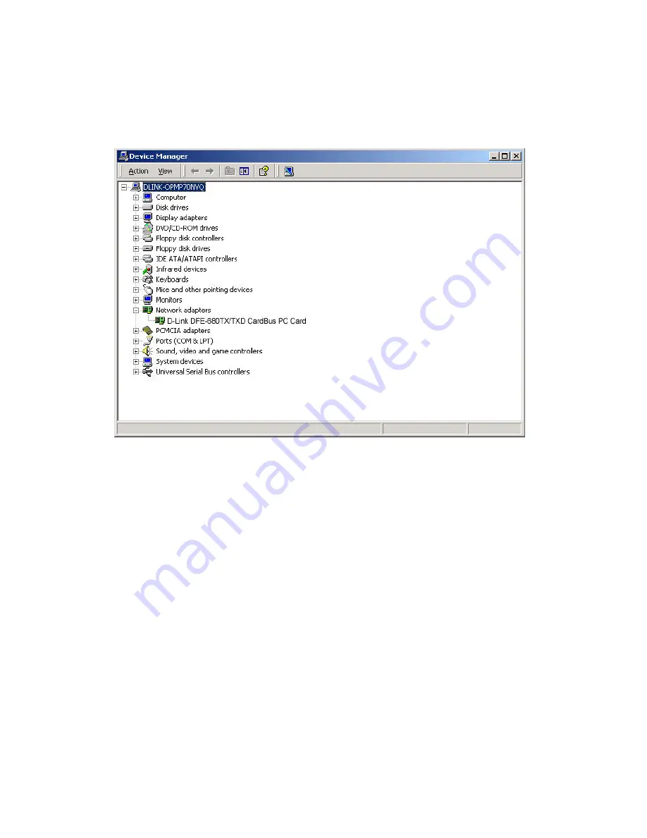
Страница 23: ...21 Figure9 The Device Manager menu Double click on the Network Adapters and the D Link DFE 680 CardBus should appear showing proper installation ...

Страница 24: ...22 Windows ME driver installation Figure1 Insert the DFE 680TX into available PCMCIA slot Windows should detect Card The Add New Hardware windows appears select Next ...

Страница 25: ...23 Figure2 Enter CD ROM drive letter or click on the Browse button and highlight the CD ROM drive under Drivers ThenClick Next to continue the installation ...

Страница 26: ...24 Figure3 A screen appears telling you that is has located the DFE 680TX driver in the CD ROM drive Then click Next Windows will copy files to the hard drive ...

Страница 27: ...25 Figure4 Click Finishto complete driver installation ...

Страница 28: ...26 Figure5 Click the start button Settings Control Panel Click the Systembutton Device Manager Network Adapters And D Link DFE 680TX CardBus should appear showing proper installation ...

Страница 29: ...27 Windows 98 Driver install Figure1 Select Next ...

Страница 30: ...28 Figure2 Select Next ...

Страница 31: ...29 Figure3 Enter CD ROM drive or click on the Browse button and select CD ROM drive ...

Страница 32: ...30 Figure4 Driver file name select Next Figure5 Insert 98 CD ROM then click on OK button ...

Страница 33: ...31 Figure6 Enter CD ROM drive then type D Win98 in the box Some computers will have the Windows 98 files available in the C Windows options cabs directory After typing in the location Click OK ...

Страница 34: ...32 Figure7 Finish ...

Страница 35: ...33 Figure8 Click the Start button Setting Control Panel Click theSystembutton Device Manager Network Adapters Device Manager will display of proper installation of adapter ...

Страница 36: ... your Network Adapter were not installed including the Network System Software or Device drivers your network will not function properly Use these steps to verify that your Network Adapter are properly installed 1 Double Click the System icon in the Control Panel 2 Click the Device Manager tab on top of the System Properties dialog box 3 Double Click Network Adapters if you do not see any items br...

Страница 37: ...onnected from its DFE 680TX with a Category 5 cables Examine the network cables and ensure that they have not been damaged by walking on rolling over chairs or closed in doors Additionally make note of and alleviate any possible electromagnetic interference that may be effecting your network Your network cables can be plugged into any port on your hub except the Uplink port The Uplink port is only...

Страница 38: ...in your DFE 680TX Network Adapters or connection 1 Restart your computer in MS DOS mode Click Start then Shut Down and finally select Restart the computer in MS DOS mode 2 Insert the CD Rom labeled DFE 680TX PCMCIA Ethernet Adapter Driver Program into your CD Rom D 3 Type D DIAG EXE at the MS DOS prompt and press Enter to start the D Link PCMCIA Fast Ethernet Adapter Diagnostic Program 4 Read the ...

Страница 39: ... computers on the network must have a unique IP address getting a reply means that a computer is on the network and that can communicate If you cannot ping another computer then there is probably a problem with the hardware Check the cabling and adapter installation If you are unable to network even when you receive a reply to your ping it is probably a software configuration issue Verify that all...

Страница 40: ...egotiation functionality Media interface RJ 45 LAN Chip Set ADMTEK AN985L EMI Certifications FCC Class B VCCI Class B CE Certification Host interface CardBus I O base address assigned by Plug and Play system Interrupt Number Assigned by Plug and Play system Physical Dimensions 85 6 54 0 3 0 mm Environment Storage 20 to 70 C 4 to 158 F Operating 0 to 60 C 32 to 140 F Humidity 10 to 90 non condensin...

Страница 41: ...Packet Driver for Winsock Packet Driver for FTP PC TCP Check http www dlink comfor newest releases of drivers D Link provides free technical support North American customers can contact D Link technical support through our web site e mail or by phone North American technical support is available Monday through Friday from 6 00 a m to 6 00 p m PST Web http www dlink com tech E mail tech dlink com P...

Страница 42: ...the following measures Reorient or relocate the receiving antenna Increase the separation between the equipment and receiver Connect the equipment into an outlet on a circuit different from that to which the receiver is connected Consult the dealer or an experienced radio TV technician for help Shielded interface cablesmust be used in order to comply with emission limits You are cautioned that cha...

Страница 43: ...ii VCCI Warning ...

Страница 44: ...er still owns the product Product purchased or delivered outside the USA One 1 Year Power Supplies and Fans One 1 Year Spare parts and spare kits Ninety 90 days D Link s sole obligation shall be to repair or replace the defective Hardware at no charge to the original owner Such repair or replacement will be rendered by D Link at an Authorized D Link Service Office The replacement Hardware need not...

Страница 45: ...eturned to an Authorized D Link Service Office for each D Link product within ninety 90 days after the product is purchased and or licensed The addresses telephone fax list of the nearest Authorized D Link Service Office is provided in the back of this manual FAILURE TO PROPERLY COMPLETE AND TIMELY RETURN THE REGISTRATION CARD MAY AFFECT THE WARRANTY FOR THIS PRODUCT Submitting A Claim Any claim u...

Страница 46: ...LIED WARRANTY CANNOT BE DISCLAIMED IN ANY TERRITORY WHERE A PRODUCT IS SOLD THE DURATION OF SUCH IMPLIED WARRANTY SHALL BE LIMITED TO NINETY 90 DAYS EXCEPT AS EXPRESSLY COVERED UNDER THE LIMITED WARRANTY PROVIDED HEREIN THE ENTIRE RISK AS TO THE QUALITY SELECTION AND PERFORMANCE OF THE PRODUCT IS WITH THE PURCHASER OF THE PRODUCT Limitation of Liability TO THE MAXIMUM EXTENT PERMITTED BY LAW D LIN...

Страница 47: ...or consequential damages or limitations on how long an implied warranty lasts so the foregoing limitations and exclusions may not apply This limited warranty provides specific legal rights and the product owner may also have other rights which vary from state to state ...

Страница 48: ...toll free HELP LINE 00800 7250 4000 toll free REPAIR LINE 00800 7250 8000 INDIA D LINK INDIA Plot No 5 Kurla Bandra Complex Road Off Cst Road Santacruz E Bombay 400 098 India TEL 91 22 652 6696 FAX 91 22 652 8914 URL www dlink india com E MAIL service dlink india com ITALY D LINK MEDITERANEO SRL Via Nino Bonnet No 6 b 20154 Milano Italy TEL 39 02 2900 0676 FAX 39 02 2900 1723 URL www dlink it E MA...

Отзывы: