background image

RZN 4503-T

RZN 4503-T

99.825.18 2.1/10/13

99.825.18 2.1/10/13

28

/

36

29

/

36

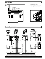
Connection of smoke vent buttons

Max. 8 buttons per line connectable.

Standard connection

Parallel connection

Parallel connection of 2x 2 buttons

2

8

3

1

6

4

7

5

R

T

 45

first to penultimate

 button

2

8

3

1

6

4

7

5

RT 45

2

8

3

1

6

4

7

5

OK

last button

Line 

T

K

A

Z

S

RZN 4503-T

Line

Control

Alarm

CLOSE

RM

10k

W

Failure

Alarm

Control

Line 

CLOSE

Failure

n.c.

RT

Line 

n.c.

Failure

T

K

A

Z

S

RZN 4503-T

Line

Control

Alarm

CLOSE

RM

10k

W

Alarm

Control

Line

Line

CLOSE

Failure

*

*

* Shunt connection by customer

Alarm

Control

Line 

CLOSE

Failure

n.c.

RT

2

8

3

1

6

4

7

5

RT 45

2

8

3

1

6

4

7

5

OK

2

8

3

1

6

4

7

5

RT 45

2

8

3

1

6

4

7

5

OK

2

8

3

1

6

4

7

5

R

T

 45

2

8

3

1

6

4

7

5

R

T

 45

first to penultimate 

button each

last button each

Line 

n.c.

Failure

T

K

A

Z

S

RZN 4503-T

Line

Control

Alarm

CLOSE

RM

Alarm

Control

Line

Line

CLOSE

Failure

*

*

Alarm

Control

Line 

CLOSE

Failure

n.c.

RT

* Shunt connection by customer

10k

W

2

8

3

1

6

4

7

5

RT 45

2

8

3

1

6

4

7

5

OK

2

8

3

1

6

4

7

5

RT 45

2

8

3

1

6

4

7

5

OK

= Display flashing

= Display ON

= Display OFF

Servicetimer is up

Line deactivated

Line fault

Display 

"line fault"

Display 

"system 

OK"

Display 

"general 

fault"

Description

If the LED line fault flashes, the line is switched off, 
e.g. for service reasons. You cannot activate the 
control panel in this status.
In case of an actual line error the LED line fault is 
permanently on.

Triggerng an alarm is not possible during the 
shutdown.

Hold 3 s to switch 
off line / tip on to 
switch on

Line shutdown

RZN 4503-T

RM

RT

R

Line

Operating contact

Alarm resistor
1k

W

BMZ / BMA 

Line 

Terminal resistor*
10k

W

E

B

Reset by BMZ

(optional)

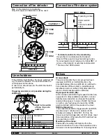
Connection of fire detector

Max. 14 fire detectors connectable.
Only D+H approved detectors must be used.

*  Terminal resistors for line monitoring

 It is pinched in control panel for transport.
 Take it off there and connect according to plan.
 Terminal resistor must remain at terminal RM 1,2,
 when no fire detector or external control exists!
** Remove the 180R resistor

Connection of fire alarm system 

< optional >

Terminal resistor*

180R

1

2

3

4

5

6.

7

**

180R

1

2

3

4

5

6.

7

**

first to penultimate 

fire detector

last

fire detector

10k

W

RZN 4503-T

RM

RT

1

2

Line

FO 1362
or
FT 1262

FO 1362
or
FT 1262

Group output:

Three minutes after the motor group has been 
operated in OPEN or CLOSE direction, the 
potential between Mot.a and Mot.b is switched to 
zero potential. While an alert, a possible group 
disturbance will not notified. Only after reset the 
alarm, a fault message will be indicated.

High-speed function (HS):

All D+H drives with SHEV high-speed function are 
supported. In daily ventilation operation, a consi-
derable noise reduction is achieved through the 
reduced drive speed. In case of SHEV the drives 
run with a very high speed to reach the OPEN 
position defined within 60 seconds at the most.

SHEV retriggering:

 The smoke vents will be triggered with an OPEN- 
impulse every 2 minutes for a duration of 30 
minutes according to VdS 2581. For this, the 
drives must be blockage safe. All D+H drives meet 
this precondition. Otherwise the DIP switches has 
to be switched on OFF.

Mounting of the drives:

Please take mounting informations from the 
relevant instruction for use of the respective drive, 
because of varied possibilities for choosing drives.

Drives

English

English

Содержание RZN 4503-T

Страница 1: ...triebsanleitung Seite 3 en Table of contents Page 2 Original instructions Page 19 99 825 18 2 1 10 13 Anerkennungs Nr approval no orange G 509006 0846 2010 EN 12101 10 2005 AC 2007 conform 0786 CPD 50...

Страница 2: ...triebnahme 14 Bedienung 15 17 berpr fung Wartung 18 Table of contents Introduction Assembly scheme 19 Intended use Safety notes 20 SHEV opening 20 Servicetimer 20 Important regulations Repair and clea...

Страница 3: ...teure unter Beachtung der technischen Richtlinien und Vorschriften installiert werden Pers nliche bergabe und die Einweisung der Nutzer inbegriffen Wartung und Instandsetzung Jeder Geb udebetreiber is...

Страница 4: ...er Technische Daten beschriebene Produkt mit den folgenden Richtlinien bereinstimmt 2004 108 EG 2006 95 EG 89 106 EG Technische Unterlagen bei D H Mechatronic AG D 22949 Ammersbek Thomas Kern Maik Sch...

Страница 5: ...HxT 156 x 232 x 83 mm VdSAnerkennungs Nr G 509006 nur orange D HAntriebe mit RWA Schnelllauf HS werden unterst tzt Der Gesamtstrom der Zentrale darf dabei nicht berschritten werden Technische Daten 24...

Страница 6: ...RZN 4503 T 99 825 18 2 1 10 13 6 36 3x 3x 2 4 1 2 3x Einbau RWA Zentrale Linie Netz Gruppe Kabelausbruch 110 183 203 ca 1 36 m Fu boden 1 3 Deutsch...

Страница 7: ...ZN 4503 T 99 825 18 2 1 10 13 7 36 RAUCHABZUG SAVUNPOISTO R G L E M ODDYMIANIE ROOKAFVOER R KVENT DESENFUMAGE EVACUACI N DE HUMOS 5 Einbau RWA Zentrale Schlagscheibe 6 Akku anschliessen Akku 7 Deutsch...

Страница 8: ...cherung ANTRIEBE F 2 5 A Netzanschluss Klemmenbelegung siehe rechts OK Melderelais Werkseinstellungen bersicht Bedienelemente r e w o P C A V 0 3 2 ry te at B Detector Line Drive Group Module Connecto...

Страница 9: ...die Antriebe wieder automatisch zu Mittels PDA Servicetool kann die L ftungszeit ge ndert werden 7 ON Netzausfall ZU Nur wenn DIP Schalter 1 ON Wenn die Netzversorgung ausf llt l uft der Antrieb zu 8...

Страница 10: ...l angegeben Erfragen Sie diese bitte bei Ihrem D H Partner Kabelverlegeplan Muster Kabel Gruppe Zentrale Antrieb Mindestens dreiadrige Ausf hrung 2 Adern f r die Versorgung des Antriebes 1 Ader f r di...

Страница 11: ...Alarm zu Mot b Mot a berwachung AUF ZU Aufmeldung nur bei LT 43U SD RM LT 10kW St rung Alarm Kontrolle Linie ZU St rung n c RT MOT 2 7 FO 1362 10kW 4 OK L N Z LT 84 U SD L P EM 47 K 2x47kW BK BK OG M...

Страница 12: ...RZN 4503 T Linie Kontrolle Alarm zu RM 10kW Alarm Kontrolle Linie Linie ZU St rung bauseitige Rangierverbindung Alarm Kontrolle Linie ZU St rung n c RT 2 8 3 1 6 4 7 5 RT 45 2 8 3 1 6 4 7 5 OK 2 8 3 1...

Страница 13: ...Anschluss Brandmeldeanlage wahlweise Endwiderstand 180R 1 2 3 4 5 6 7 180R 1 2 3 4 5 6 7 erster bis vorletzter Brandmelder letzter Brandmelder 10kW RZN 4503 T RM RT 1 2 Linie FO 1362 oder FT 1262 FO 1...

Страница 14: ...sst rungen zu rechnen Folgende Anschl sse berpr fen Netz 230V Antriebe RT Taster ggf Brandmelder und L ftertaster Siehe Anschlusspl ne Seite 11 13 Auslieferungszustand der DIP Schalter siehe Seite 9 W...

Страница 15: ...Fremdansteuerung RAUCHABZUG OK RAUCHABZUG RZN RT OK Manuelles ffnen durch Rauchabzugstaster Automatisches ffnen durch Brandmelder Automatisches ffnen durch Fremdansteuerung z B Brandmeldezentrale RZN...

Страница 16: ...er BeiAusl sung durch Brandmelder oder Fremdansteuerung click Kontakt der Fremdansteuerung OK o d e r o d e r OK o d e r Bedienung Schlie en nach Alarm ffnen der Geh use Zentrale und Taster mit Hilfe...

Страница 17: ...t einem optionalen Automatikschalter abgeschaltet werden Ist kein Automatikschalter vorhanden ist Spalt l ftungsbetrieb bei schlechtem Wetter nicht m glich Wenn die Wetterautomatik eingeschaltet ist l...

Страница 18: ...Rauchabzug muss sich ffnen Warten bis kein Rauch mehr im Melder ist oder Kontakt in Fremdanlage ffnen z B durch R ckstellen der Brandmeldeanlage Linie in Zentrale Zur cksetzen Druckschalter aus einsch...

Страница 19: ...sposal to professionally install your system and commission it Our partner system guarantees that D H products are installed exclusively by trained and experienced fitters in compliance with the techn...

Страница 20: ...95 EC 89 106 EC Technical file at D H Mechatronic AG D 22949 Ammersbek Thomas Kern Maik Schmees Member of the Board Authorized signatory Technical Director 22 12 2010 Declaration of Conformity Observ...

Страница 21: ...mperature range 5 40 C Dimensions WxHxD 156 x 232 x 83 mm VdSApproval No G 509006 only orange D H Highspeed HS drives will be supported The total current of the control panel must not be exceeded Tech...

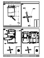
Страница 22: ...RZN 4503 T 99 825 18 2 1 10 13 22 36 3x 3x 2 4 1 2 3x Mounting of SHEV control panel Line Mains Group Cable breakout 110 183 203 ca 1 36 m Floor 1 3 English...

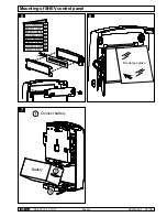
Страница 23: ...T 99 825 18 2 1 10 13 23 36 SMOKE VENT SAVUNPOISTO R G L E M ODDYMIANIE ROOKAFVOER R KVENT DESENFUMAGE EVACUACI N DE HUMOS 5 Mounting of SHEV control panel Break type glass 6 Connect battery Battery 7...

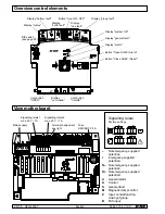
Страница 24: ...ON Display system OK DIP switch see page 25 Display mains Display alarm Display group fault Display battery fault Display earth fault Display line fault Display general fault Display not closed Vent...

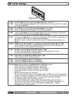
Страница 25: ...ose again after the time set factory set 10 min This time can be edited by the PDA servicetool 7 ON Power failure CLOSE Only if DIP switch 1 ON In case of power failure the drives will close 8 ON Inte...

Страница 26: ...Please consult your D H partner Wiring plan Paragon Group cable control panel drive At least three wire design 2 wires for the supply of the drive 1 wire for line monitoring on which also the SHEV hig...

Страница 27: ...CLOSE Mot b Mot a Monitoring OPEN CLOSE Open signal only withLT 43U SD RM LT 10kW Failure Alarm Control Line CLOSE Failure n c RT MOT 2 7 FO 1362 10kW 4 OK L N Z LT 84 U SD L P EM 47 K 2x47kW BK BK O...

Страница 28: ...e T K A Z S RZN 4503 T Line Control Alarm CLOSE RM 10kW Alarm Control Line Line CLOSE Failure Shunt connection by customer Alarm Control Line CLOSE Failure n c RT 2 8 3 1 6 4 7 5 RT 45 2 8 3 1 6 4 7 5...

Страница 29: ...l Terminal resistor 180R 1 2 3 4 5 6 7 180R 1 2 3 4 5 6 7 first to penultimate fire detector last fire detector 10kW RZN 4503 T RM RT 1 2 Line FO 1362 or FT 1262 FO 1362 or FT 1262 Group output Three...

Страница 30: ...of components can cause malfunction Check following connections mains 230 V drives smoke vent buttons when necessary fire detectors and vent buttons See wiring an connection plans pages 27 29 Deliver...

Страница 31: ...xternal control SMOKE VENT OK SMOKE VENT RZN RT OK Manual opening by smoke vent button Automatic opening by fire detector Automatic opening by external control e g fire alarm system RZN RT OK SMOKE VE...

Страница 32: ...case of automatic release by fire detector or external control click External control OK o r o r OK o r Operation Closing after alarm Open the housings control panel and buttons using the enclosed ke...

Страница 33: ...c switch if gap ventilation is required in case of bad weather Gap ventilation is not possible in case of bad weather if no automatic switch available If the weather automatic is switched on the syste...

Страница 34: ...onitored alarm indication and remote controls Inspection Check all appliances and cable connections for outer damage and dirt accumulation Fire detectors smoke vent buttons smoke vents and so on must...

Страница 35: ...RZN 4503 T 99 825 18 2 1 10 13 35 36...

Страница 36: ...40 605 65 Fax 40 605 65 254 Germany 49 239 49 E Mail info dh partner com www dh partner com 99 825 18 2 1 10 13 2013 D H Mechatronic AG Ammersbek Technische nderungen vorbehalten Rights to technical...

Отзывы: