background image

31

Crossover Filter Slopes

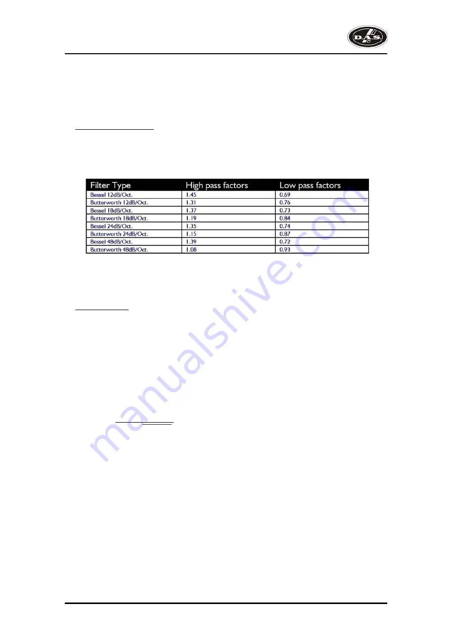
It should also be noted that the turnover frequency displayed on the screen is the -3dB point for all types 

except   Linkwitz-Riley where the -6dB point is shown. If the -6dB point is to be used for the Bessel or 
Butterworth filter, take the required crossover frequency, multiply this by the appropriate factor from the 
following table and then select the closest available frequency on the display.

Please note that unlike conventional analogue crossovers, crossover points and slopes are set with 

absolute accuracy since component tolerance problems do not occur.

Please see page 12 for details of how to adjust the high and low pass crossover filter settings.

Time Alignment

A further advantage of the 

DSP-2060A

 over conventional products is the provision of an independently 

adjustable delay section for each output. This allows the true arrival time from multiple drivers to precisely 
aligned rather than relying on the compromise 'phase adjust' approach. Delay time is adjustable in 0.3uS 
steps (0.1mm).

Please see page 12 for details of how to adjust the delay times.

To convert from units of time (i.e. milliseconds) to units of distance use the following formula:

1 millisecond = 343mm (1.126ft) @ 20Cº (68Fº) 

To calculate time delay for a known distance, use:

Time delay = Distance (in metres)

               20.06 x  273 + ºC

where ºC is the temperature in ºC.

To simplify this equation at 20Cº.

Delay (in mS) = 0.955 x Distancia (in feet)
(Distance in metres x 2.192) or (Distance in feet x 0.955)

Note: [ºC] = 0.5555 x ([ºF]-32)

DSP-2060A

User’s Manual

Содержание DSP-2060A

Страница 1: ...utilizar el equipo lea la sección Precauciones de seguridad de este manual Conserveestemanualparafuturasconsultas Before operating the device please read the Safety precautions section of this manual Retainthismanualforfuturereference ...

Страница 2: ...DSP 2060A ...

Страница 3: ...ligrosos no aislados Para reducir el riesgo de choque eléctrico no retire la cubierta Aparato de Clase I por tanto debe estar conectado a tierra Safety Precautions Precauciones de Seguridad Keep these instructions Heed all warnings Follow all instructions The exclamation point inside an equilateral triangle indicates the existence of internal components whose substitution may affect safety The ON ...

Страница 4: ...n en garantía es imprescindible que el producto no haya sido previamente manipulado e incluir una fotocopia de la factura de compra GARANTÍA All D A S products are warrantied against any manufacturing defect for a period of 2 years from date of purchase The warranty excludes damage from incorrect use of the product All warranty repairs must be exclusively undertaken by the factory or any of its au...

Страница 5: ...va RoHS 2002 95 CE l Directiva RAEE WEEE 2002 96 CE Y es conforme a las siguientes Normas Armonizadas Europeas In accordance with Harmonized European Norms l EN 60065 2002 Audio video and similar electronic apparatus Safety requirements l EN 55103 1 1996 Electromagnetic compatibility Product family standard for audio video audio visual and entertainment lighting control apparatus for professional ...

Страница 6: ...DSP 2060A User s Manual ...

Страница 7: ...s Editing audio parameters Output channels Input ganging and output ganging Memory structure Remote control interface operation AES inputs and outputs AES diagnostics and status information Security and locking Advanced audio features Specifications Quick reference 3 4 5 6 11 12 15 16 18 23 24 25 27 35 36 DSP 2060A User s Manual ...

Страница 8: ...DSP 2060A User s Manual ...

Страница 9: ...p 192kHz TM They may be controlled externally by XTA s proprietary Windows software along with existing and future AudioCore products To achieve this the units have up to two inputs and six outputs which can be configured in a selection of basic crossover modes 2 x 3 way 2 x 2 way 2 Aux and 1 x 6 way as applicable to i o configurations They also offer a free assign mode which allows completely fle...

Страница 10: ...sensitive encoders adjust the relevant parameters as displayed on the screen Status LEDs The two status LEDs show from left to right AES inputs selected flashing if not locked and AES outputs selected Input Sections Control and monitor input signal paths Red MUTE buttons illuminate when pressed and mute audio for that channel EDIT buttons illuminate yellow when pressed and access gain on first pre...

Страница 11: ...rol data over long distance or multiple unit applications See page 18 for more information 4 Audio Outputs 3 pin XLR sockets are provided for each channel All are fully balanced pin 2 hot 3 cold 1 screen Note the legending on the panel to designate which outputs are used for AES streams when the digital outputs are enabled Please see page 23 for more information 6 Audio Inputs 3 pin XLR sockets ar...

Страница 12: ...nd use the BACK or NEXT key to select Crossover sub menu and then press ENTER Use the BACK or NEXT key to select Design a crossover and then press ENTER Finally use the BACK or NEXT key to select the desired routing and follow the set up wizard to finalise your design Note that when in a menu ENTER is always used to confirm selections The current selection is marked with an asterisk Use the EDIT k...

Страница 13: ...Input Channel Makeup The diagram below shows the processing available on each of the two input channels before routing to the matrix Output Channel Makeup The diagram below shows the processing available on each of the six output channels after routing from the matrix Preset Routing Configurations In addition to the ability to assign any combination of inputs to any output a number of preset confi...

Страница 14: ...put by default with output 5 being bandwitdth limited as a sub output SUB 15Hz 120Hz LOW OUTPUT 40 1Hz 1 62kHz LOW OUTPUT 40 1Hz 1 62kHz HIGH OUTPUT 1 62kHz 22 2kHz HIGH OUTPUT 1 62kHz 22 2kHz AUX 10Hz 32kHz Σ 2 x 3 way crossover As shown each input feeds a pair of outputs odd numbers being the low frequency split and even numbers being the high part of the spectrum Default suggested crossover fre...

Страница 15: ...9 1 x 6 way crossover Inputs A is fed to all eight outputs with initial settings being all full bandwidth with input B unused The crossover points can be adjusted as desired DSP 2060A User s Manual ...

Страница 16: ...ent configuration is set to Press BACK until the display shows Design A Crossover Routing Free Assign And then press ENTER The EDIT key will illuminate for output 1 as will any relevant input EDIT keys showing which inputs are feeding output 1 The display will also detail the current combination of inputs feeding this output To change the routing for any output press its EDIT key and then choose t...

Страница 17: ...ametric EQ The display shows IPA Input A Gain Input Gain 6 0dB IPA Input A Delay Base Delay 0 00mS IPA Input A PEQ 1 1k00Hz Q 3 0 0 0dB The GAIN allows to change its value Pressing ENTER to confirm Note The delay steps are 1mS 343mm through FREQ or 10uS 4mm through Q encoder There are eight bands of parameter equalisation available on every input The behaviour of each individual band can be change...

Страница 18: ...n inverted phase Output delay The maximum available delay between any input and output is 650mS For example if the input delay on channel A is set to 500mS the maximum available output delay for any output fed from input A will be 150mS The readout units can be changed between time in milliseconds distance in feet or distance in metres OP1 Output 1 Delay Delay 0 0000mS Note The delay steps are 1mS...

Страница 19: ... Low Freq Overlap will be displayed Note that to access the 48dB Octave filters parametric bands 6 7 need to be bypassed or set to 0dB If they are not the message Bypass PEQ s 6 7 To Access 48dB Slopes will be displayed High Low Freq Overlap will be displayed Note that to access the 48dB Octave filters parametric bands 8 9 need to be bypassed or set to 0dB If they are not the message Bypass PEQ s ...

Страница 20: ... be exceeded The release time can be automatically linked to the high pass filter frequency so that it is set to a value appropriate for the output s frequency range If this feature is enabled the display will show Rel Auto in place of the release time Selection of automatic time constants is through the Design a Crossover wizard in the Crossover Sub menu More information about the limiters and th...

Страница 21: ... must be selected and then ganged to 3 Ø Outputs cannot share more than one ganging set so for example output 3 cannot be ganged to 2 and 4 unless they are ganged together as well Effectively 3 and 4 are ganged to 2 in this case With these rules in mind selecting and setting up gangs is quite straightforward Press a MUTE key to choose the output to gang its LED will begin to flash and an EDIT key ...

Страница 22: ...Y Sub Menu and its operation warrants a little more explanation Selecting to STORE or RECALL using the GLOBAL MEMORY Sub Menu option offers the possibility of storing various combinations of the available memory types and these are selected using the BACK and NEXT keys To explain how this all works please consider the following example There are 10 memories stored in the unit with various combinat...

Страница 23: ...ge all the parameters Note that storage and erasure of memories does not follow quite the same rules being simpler in its operation Selecting Input and Crossover during a Store will skip any memories that have other combinations in them Selecting Erase for any combination will show only locations that have EXACTLY that combination it is not possible to erase just one part of a combination memory T...

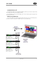
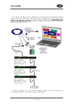
Страница 24: ...onnected to the computer via this interface Additional units may be daisy chained via the RS485 connections from the back of the first one it acting as a converter for them but their RS232 ports are not used RS232 Connection Single Unit A typical interface set up might involve running an RS232 link from laptop or a desktop computer to a DSP 2060A unit set up as a master unit The diagram below show...

Страница 25: ... Units If control over multiple units is required typically the slaves will be set up to run from the RS485 ports on the master unit Note the incremental ID NUMBER option in the unit s interface setup DSP 2060A Interface Sub Menu Mode RS232 Mode SERIAL SPEED 115200 Stop MIDI Prog Chng Yes Remote ID Number 1 DSP 2060A Interface Sub Menu Mode RS485 Mode SERIAL SPEED 115200 Stop MIDI Prog Chng Yes Re...

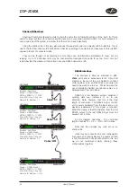
Страница 26: ...ielded microphone cables or a balanced feed from a multicore RS485 is a fully balanced system capable of sending data over distances of up to one kilometre Note however that this is the total length of connection The RS485 output of each unit is purely hardwired from the input and so no electrical regeneration of the signal is provided What this means is that the distance from the first RS485 outp...

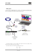
Страница 27: ... adapter the XLR to 9 pin adapter and the converter itself This complete kit is part number INT 485 If you need to make up one of the XLR to 9 pin adapters the pin out is XLR D type 1 1 2 3 3 8 Additional DSP 2060As may be set up as slaves with incremental ID numbers as necessary OR via wireless with Walkabout Pack II KIT Please see your manual available from our website DSP 2060A Interface Sub Me...

Страница 28: ...s used with the standard converter The adapter is available in a kit which includes a USB Serial converter the XLR to 9 pin adapter and the K2 ADE converter itself This complete kit is part number USB 485 DSP 2060A Interface Sub Menu Mode RS232 Mode SERIAL SPEED 115200 Stop MIDI Prog Chng Yes Remote ID Number 1 DSP 2060A Interface Sub Menu Mode RS485 Mode SERIAL SPEED 115200 Stop MIDI Prog Chng Ye...

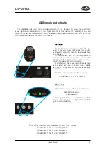
Страница 29: ...panel of the unit A red LED inside this aperture illuminates to show that the AES digital inputs have been selected A complimentary LED on the front panel also illuminates The switch controls the rear panel LED directly whilst the front panel one is via the processor allowing it to relay a little more information If it is flashing this means that AES inputs have been selected but have not locked O...

Страница 30: ...and is of no importance to the user Pressing ENTER again will show This display shows the status of the AES receiver input A The sample rate the unit has been able to lock to is shown or UNLOCKED will be displayed in its place The unit will lock to sample rates from 32kHz up to and including 192kHz The unit s own processing sample rate is 96kHz and AES output data is always at 96kHz Internal sampl...

Страница 31: ... active Xover Trim Mute As for Xover Trim but additionally output mutes are locked Input mutes remain active Changes Only All parameters may be viewed but none may be adjusted This applies to both inputs and outputs All mutes remain active Changes Views No parameters are accessible in effect the EDIT keys do nothing All mutes remain active Changes Mutes All parameters may be viewed but none may be...

Страница 32: ...omentarily After a few seconds the unit will ask for a security code Use the EDIT keys in the same manner as for entering lock codes see page 25 for details and enter 2121 The display will show Enter XTA Supplied Code Break Code 12345 NNNN The Break Code in the example 12345 should be noted and supplied to DAS We have software to generate the corresponding Pass Code which should be typed in follow...

Страница 33: ...er may sound awful In particular as with all limiters using too fast an attack or release time will result in excessive low frequency distortion In the Design a Crossover sub menu there is an option for automatic limiter time constants Use this option if you are unsure how to set the time constants manually We recommend the use of the automatic setting In this mode the time constants will be autom...

Страница 34: ...n turning the signal down will be in the order of several hundred milliseconds at best This will only be true if he is not distracted in reality it may be several seconds before any gain reduction is imposed on the signal to bring it under control For an analogue dynamics processor the situation is much better Controlling the gain electronically and not relying on a human sidechain feedback mechan...

Страница 35: ...ve similar results but with the penalty of delaying the main signal by the amount of look ahead delay introduced The D Max limiter which appears in output lists just following the traditional limiter has only two parameters to adjust Op1 Output 1 ClipLim Rel Medium 10dB Above The release time either Fast Medium or Slow and the threshold Note that the threshold is set to be a minimum of 2dB above t...

Страница 36: ...he speaker manufacturer s specification Have a release time which is sufficiently long to avoid the limiter itself modulating the program Be intelligent enough to adjust the envelope of the limiter according to the frequency content of the program material The program limiters are capable of performing all these tasks The only parameter that the user must set manually is the threshold and it is cr...

Страница 37: ...sover filter settings Time Alignment A further advantage of the DSP 2060A over conventional products is the provision of an independently adjustable delay section for each output This allows the true arrival time from multiple drivers to precisely aligned rather than relying on the compromise phase adjust approach Delay time is adjustable in 0 3uS steps 0 1mm Please see page 12 for details of how ...

Страница 38: ...omatically set the gain back to 0dB Each filter type will be explained in turn in the following section Standard Parametric EQ InA Input A PEQ 1 1k00Hz Q 3 0 0 0dB The standard parametric band has adjustable frequency Q or Bandwidth and Gain controls These affect a range of frequencies symmetrically about the centre freqency as shown in the graph Various levels of cut and boost are shown to the le...

Страница 39: ...ymetrical responses may be achieved by adjusting the Q of each filter independently Shelving EQ High Shelf shown InA Input A HSF 1 1k00Hz Q 3 0 0 0dB Remember to change filter types press BYPASS to bypass the filter and then use ENTER to select the filter type The shelving EQ has adjustable frequency Q or Bandwidth and Gain controls These affect a range of frequencies from the turnover freqency as...

Страница 40: ...rol adjust the damping of the filter so that low Q settings show less overshoot at the turnover frequency but also slower roll off Remember that Q is 1 Bandwidth so the higher the Q the lower the Bandwidth and the smaller the range of frequencies affected The filter is primarily 12dB Octave but in achieving this sort of roll off with a high Q value will result in quite a large overshoot in level a...

Страница 41: ... 20dBm into 600 ohms MUTE ON OFF Frequency Resp dB 20Hz 20kHz Dyn Range 116dB 20Hz 20k unweighted Distortion 02 1kHz 18dBm Maximum Delay 650 mS Min Step Size 0 3uS Input Gain 6dB to 40dB in 0 1dB steps Output Gain 15dB to 40dB in 0 1dB steps Parametric Equalisation 8 per Input 9 Sections per Output Filter Gain 15dB to 30dB in 0 1dB steps Freq Range 19 7Hz 32kHz 1 36 octave steps Filter Q BW 0 4 to...

Страница 42: ...up output ganging INTERFACE Sub menu Comms interface setup RS232 and RS485 G P I interface configuration and wireless interface SYSTEM Sub menu Used to view unit s status and select various global options such as PEQ Q or bandwidth units delay units and output metering point pre post mute SECURITY Sub menu Used for locking various operations of the unit using a 4 digit code AES EBU Sub menu Switch...

Страница 43: ......

Страница 44: ... 888DAS4USA Tel 1 305 436 0521 Fax 1 305 436 0528 D A S AUDIO ASIA PTE LTD 25 Kaki Bukit Crescent 01 00 02 00 Kaki Bukit Techpark 1 Singapore 416256 Tel 65 6742 0151 Fax 65 6742 0157 D A S AUDIO S A C Islas Baleares 24 46988 Fuente del Jarro Valencia SPAIN Tel 96 134 0525 Tel Intl 34 96 134 0860 Fax 96 134 0607 Fax Intl 34 96 134 0607 ...

Отзывы: