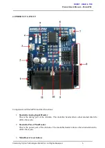
Product User’s Manual – ShieldPS2
Arduino main board will require around 30ms to ready after reset.
4.
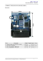
Status indicator LED (Orange)
This LED will blink and illuminate with different brightness depending on the PS2 status.
LED Condition
Description
Blink with different
brightness
Once power up, if there is no SONY PS2 controller connected or
detected..
Stay illuminated with
low brightness
SONY PS2 controller detected and communication is working fine.
Stay illuminated with
high brightness
Digital button on SONY PS2 controller is pressed.
5.
Power indicator LED (Green)
Indicator to shows that power is supplied to Cytron PS2 Shield.
6.
Baud Rate selector
To select the preferable UART baud rate For Cytron PS2 Shield to obtain latest baudrate
from selector, ShieldPS2 need to be reset to update the board’s baud rate.
7.
On board Cytron PS2 Shield reset button
PS2 RST button will only reset the SHIELDPS2 but not the Arduino Main board.
8.
Stackable Digital I/O Headers
JP4 and JP7 are Digital I/O pins stacked to the Arduino main board.
9.
RX Pin Selector
User may select D0, D2, D8 or D10 as RX pin for SHIELDPS2 with the mini jumper.
10.
TX Pin Selector
User may select D1, D3, D9 or D11 as TX pin for SHIELDPS2 with the mini jumper.
11.
SONY PS2 Connector Socket
Please connect PS2 Controller plug here, wireless or wired.
Created by Cytron Technologies Sdn. Bhd. – All Rights Reserved
7


