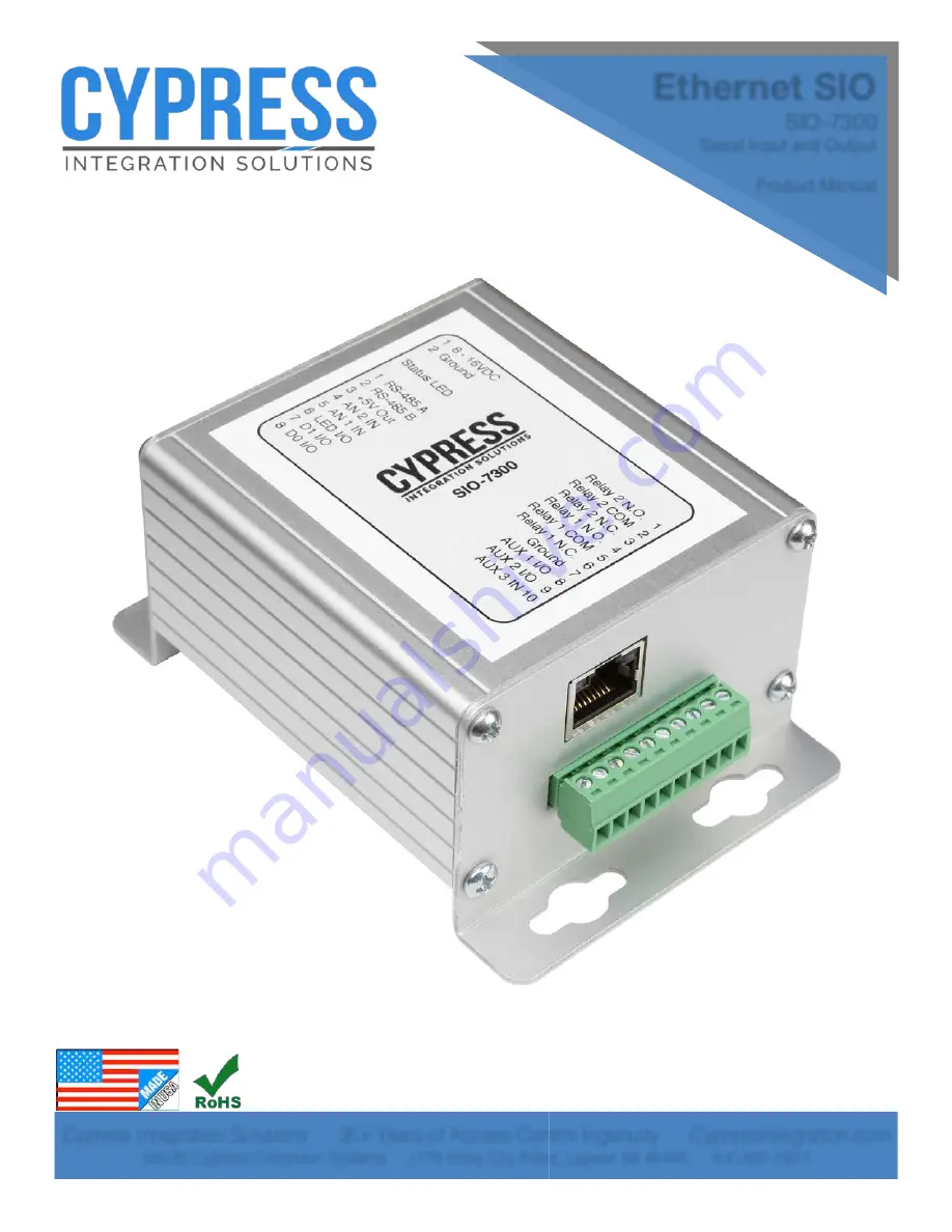
Cypress SIO-7300 Скачать руководство пользователя страница 1

Page 1


Ethernet SIO

SIO-7300

Serial Input and Output

Product Manual

Cypress Integration Solutions      35+ Years of Access Control Ingenuity      CypressIntegration.com 

©

2020 Cypress Computer Systems     1778 Imlay City Road, Lapeer, MI 48446      800-807-2977 

SIO-7300_MAN 210108

Содержание SIO-7300

Страница 1: ...Serial Input and Output Product Manual Cypress Integration Solutions 35 Years of Access Control Ingenuity CypressIntegration com 2020 Cypress Computer Systems 1778 Imlay City Road Lapeer MI 48446 800...

Страница 2: ...8 bits Strobed Falling 4 248 bits Unsupervised F 2F 4 248 bits Network Specifications Network Interface RJ45 Ethernet 10Base T or 100Base TX auto sensing Compatibility Ethernet Version 2 0 IEEE 802 3...

Страница 3: ...10 DIP Switches 11 12 Configuring Network Settings Overview and Connecting to the SIO 7300 13 15 Configuring Network Settings Connecting via Telnet 16 19 Configuring Network Settings Connecting via we...

Страница 4: ...Page 4 SIO 7300 Enclosure Dimensions Cypress SIO 7300 Unit Dimensions 0 120 X 4 3 065 2 770 4 0625 2 660 2 940 SIO 7300 Dimensions in inches...

Страница 5: ...0 pins 1 Relay 2 Normally Open 2 Relay 2 Common 3 Relay 2 Normally Closed 4 Relay 1 Normally Open 5 Relay 1 Common 6 Relay 1 Normally Closed 7 Ground 8 AUX 1 Input Output 9 AUX 2 Input Output 10 AUX 3...

Страница 6: ...Page 6 Cypress SIO 7300 Circuit Board Assembly Features DIP Switches J1 Header Status LED J2 Header J3 Header RJ45 Port Heat Sink Screw...

Страница 7: ...IO 7300 is powered on and configuration settings have been applied Flashing Green When the Network Settings are defaulted the status LED will flash green for approximately 8 seconds until the network...

Страница 8: ...7300 RJ45 LED Behavior Activity LED right Link LED left RJ45 Port Link LED left Activity LED right Color Meaning Color Meaning OFF No Link OFF No Activity Amber 10 Mbps Amber Half Duplex Green 100 Mbp...

Страница 9: ...1 8 16VDC 2 Ground Status LED 1 RS 485 A 2 RS 485 B 3 5V Out 4 AN 2 IN 5 AN 1 IN 6 LED I O 7 D1 I O 8 D0 I O Relay 2 N O 1 Relay 2 COM 2 Relay 2 N C 3 Relay 1 N O 4 Relay 1 COM 5 Relay 1 N C 6 Ground...

Страница 10: ...B 3 5V Out 4 AN 2 IN 5 AN 1 IN 6 LED I O 7 D1 I O 8 D0 I O Relay 2 N O 1 Relay 2 COM 2 Relay 2 N C 3 Relay 1 N O 4 Relay 1 COM 5 Relay 1 N C 6 Ground 7 AUX 1 I O 8 AUX 2 I O 9 AUX 3 IN 10 SIO 7300 Hos...

Страница 11: ...bit Strobed Rising Dorado 644 1 1 0 1 Set data interface to 4 248 bit Strobed Rising MagTek 1 1 1 0 Set data interface to 4 248 bit Strobed Falling 1 1 1 1 Set data interface to 4 248 bit Unsupervise...

Страница 12: ...n Mode Default DIP Switch Settings The SIO 7300 is shipped in Run Mode It is set to Data Input Mode AUX 1 and AUX 2 are set as inputs and the data interface is set to Wiegand The Network Settings are...

Страница 13: ...ot connected to or communicating with a host device while configuring the network settings The SIO 7300 should be directly connected to the computer being used to configure it Connecting to the SIO 73...

Страница 14: ...ings cont At the Network and Sharing Center click on Change adapter settings on the left side of the screen Disable any wireless network connections if any are present by right clicking the wireless n...

Страница 15: ...he Local Area Connection the Local Area Connection Properties window will appear Double click on Internet Protocol Version 4 the IPv4 Properties window will appear Select Use the following IP address...

Страница 16: ...the response from Command Prompt if Telnet is disabled If once Telnet is enabled enter the Telnet command into Command Prompt The Telnet command has two arguments the IP address and the port number T...

Страница 17: ...ul the screen will change to match the picture below Press enter to proceed to the main menu The main menu lists the sub menus Most parameters concerning the SIO 7300 are in the Server Channel 1 Exper...

Страница 18: ...Page 18 Cypress SIO 7300 Configuring Network Settings cont Below are the Server menu parameters Notably the Server menu is where the IP address is changed Below are the the Channel 1 menu parameters...

Страница 19: ...Page 19 Cypress SIO 7300 Configuring Network Settings cont Below are the Expert menu parameters Below are the Security menu parameters...

Страница 20: ...example uses Google Chrome Enter the IP address of the SIO 7300 into the address bar the default IP address of the SIO 7300 is 192 168 49 59 The web browser will prompt the user login with a username...

Страница 21: ...sub menus are located on the left side of the screen Click on Network Server and Connection to navigate to those menus When finished changing network settings click Apply Settings The SIO 7300 Ethern...

Страница 22: ...Page 22 Cypress SIO 7300 Configuring Network Settings cont Below is the Server Settings menu Below is the Connection Settings menu...

Страница 23: ...d Disabled Port 77F0h Enabled Channel 1 Baudrate 9600 I F Mode 4C Flow 00 Port 10001 Connect Mode C0 Send in Modem Mode Enabled Show IP address after RING Enabled Auto increment source port Disabled R...

Страница 24: ...rce 1 byte The address of the device from which this packet originated This begins with 0x01 plus the address of any expansion devices The host s address is 0xF1 Destination 1 byte The address of the...

Страница 25: ...uses the first byte of the message s Data Field to control the devices outputs and returns a reply with an input Data Field and status of 0x14 0x15 Command Idle 2 bytes The first byte is a bit mask to...

Страница 26: ...nt the SIO 7300 will respond using the 24 248 bit format See SIO Reader Data 0x18 Command Simulate 24 40 Bit Wiegand 6 bytes This command is only valid when the SIO 7300 is configured for Wiegand Outp...

Страница 27: ...t and clears the even parity bit leaving the facility code and badge number fields right justified in the bu er 248 Bit Reader Data This format is used when receiving reader data from the SIO 7300 in...

Страница 28: ...bytes 0x000000 at the start of every packet 0B Length 1 byte Length of the packet in bytes starting from the Length Field to the Check Sum Field excludes the Sync Field This packet is 11 bytes in len...

Страница 29: ...1 byte Address of the device the packet is being sent to The host device s address is static 0xF1 This packet is being sent from the SIO 7300 to the host device 01 Type 1 byte This field is set based...

Страница 30: ...lity Code is 18 and the Card Number is 13398 Raw output from Wiegand port 00001001000110100010101100 Raw Data 01234567890123456789012345 Bit Number Wiegand output separated by field 0 00010010 0011010...

Страница 31: ...F1 06 00 15 00 00 08 sync len srce dest type resp cmd stat data cksm 00 00 00 Sync 3 bytes Static 3 bytes 0x000000 at the start of every packet 0A Length 1 byte Length of the packet in bytes starting...

Страница 32: ...of the device the packet is being sent to The host device s address is static 0xF1 This packet is being sent from the SIO 7300 to the host device 01 Type 1 byte This field is set based on which device...

Страница 33: ...06 00 15 00 00 08 sync len srce dest type resp cmd stat data cksm Reader Data Response 0000000E01F1010600161A00002469571B Reader Data Response separated by field 00 00 00 0E 01 F1 01 06 00 16 1A 00 00...

Страница 34: ...Field is always a constant value of 0x06 00 Command 1 byte The Command Field is always a constant value of 0x00 16 Status 1 byte The Status Field shows the command response codes 0x16 is the Reader Da...

Страница 35: ...e SIO 7300 F1 Type 1 byte This field is set based on which device generated the message The host device generated this message so the Type Field is set to 0xF1 06 Response 1 byte The Response Field is...

Страница 36: ...f the device the packet is being sent to The host device s address is static 0xF1 This packet is being sent from the SIO 7300 to the host device 01 Type 1 byte This field is set based on which device...

Страница 37: ...O pin designated for LED signal The normal state is 5V high the active state is 0V low LED I O direction is opposite data interface I O direction AUX 1 I O Input or Output J3 8 Active low digital I O...

Страница 38: ...0 and the relay output is normal Commands that contain the Output Control Byte in the Data Field are the 0x09 Clear Read 0x12 Expanded Idle 0x14 Reset State and 0x15 Idle commands Input Data Bytes The...

Страница 39: ...e state is low 0V When the SIO 7300 receives a command from the host device that contains the Output Control Byte in the Data Field and bit 2 is set 1 the LED I O pin will change from the normal state...

Страница 40: ...an Auxiliary Input pin low 0V the input pin is now in the active state When an Auxiliary Input pin is in the active state 0V the next 0x15 Idle response will have the associated bit set 1 in the first...

Страница 41: ...d by bit 3 in the Output Control Byte The state of the AUX 2 I O pin is controlled by bit 4 in the Output Control Byte If the associated bit in the Output Control Byte is set 1 then the state of the o...

Страница 42: ...used as a supervised input The diagram below shows a switch and two 1K resistors connected to the AN 1 IN pin This creates four possible conditions on the AN 1 IN pin shown in the table below The four...

Страница 43: ...to the AN 2 IN pin As the temperature changes the voltage output of the thermometer changes This changed the voltage on the AN 2 IN pin providing a di erent analog value for the host device to monito...

Страница 44: ...active state When the relay control bit is not set 0 the associated relay changes to the normal state Commands that contain the Output Control Byte in the Data Field are the 0x09 Clear Read 0x12 Expa...

Страница 45: ...nected directly to the input on the door strike While Relay 1 is in the normal state Relay 1 COM and Relay 1 N O are not continuous the door strike is not activated While Relay 1 is in the active stat...

Отзывы: