CY3273 Cypress Low Voltage Powerline Communication Evaluation Kit Guide, Doc. # 001-55382 Rev. *C
21
PLC LV Evaluation Board
3.3.3
Transmit and Receive Coupling Circuit
This circuit couples the signal from the board on to the powerline. On the receive side, the same cir-
cuit couples the carrier on the powerline to the board, rejecting the low frequency power and noise
on the powerline.
The key components in this section are listed in the following table.
Table 3-3. Transmit and Receive Coupling Circuit
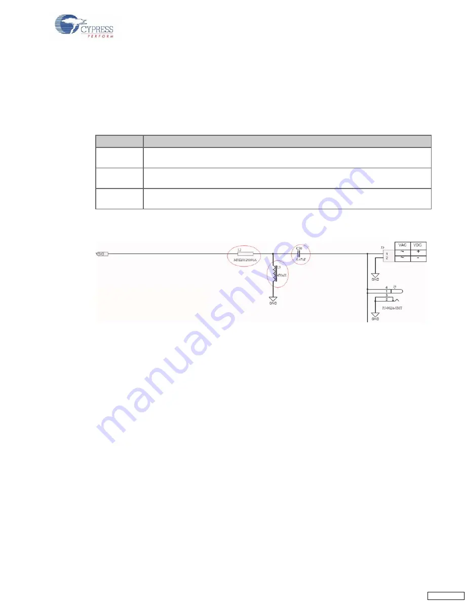
The key components are circled in the following schematic.
Figure 3-4. Transmit Amplifier Schematic
Component
Description
L2
This inductor blocks very high frequency signals (for example, FM radio ) and offsets the
impedance of capacitor C30, so as to have a lower transmit impedance.
L3
This inductor, along with C30, filters out low frequency signals (for example, 50/60 Hz AC or
DC power) and presents a high impedance to the 132 kHz PLC signal.
C30
This is the coupling capacitor that couples the PLC signal and blocks the low frequency sig-
nals. Its voltage rating must be higher than the voltage on the powerline..


