CY22392
Document #: 38-07013 Rev. *D
Page 3 of 8
Operation
The CY22392 is an upgrade to the existing CY2292. The new
device has a wider frequency range, greater flexibility,
improved performance, and incorporates many features that
reduce PLL sensitivity to external system issues.
The device has three PLLs which, when combined with the
reference, allow up to four independent frequencies to be
output on up to six pins. These three PLLs are completely
programmable.
Configurable PLLs
PLL1 generates a frequency that is equal to the reference
divided by an 8-bit divider (Q) and multiplied by an 11-bit
divider in the PLL feedback loop (P). The output of PLL1 is sent
to the crosspoint switch. The output of PLL1 is also sent to a
/2, /3, or /4 synchronous post-divider that is output through
CLKE. The frequency of PLL1 can be changed by external
CMOS inputs, S0, S1, S2. See the following section on
General-Purpose Inputs for more details.
PLL2 generates a frequency that is equal to the reference
divided by an 8-bit divider (Q) and multiplied by an 11-bit
divider in the PLL feedback loop (P). The output of PLL2 is sent
to the crosspoint switch.
PLL3 generates a frequency that is equal to the reference
divided by an 8-bit divider (Q) and multiplied by an 11-bit
divider in the PLL feedback loop (P). The output of PLL3 is sent
to the cross-point switch.
General-Purpose Inputs
S0, S1, and S2 are general-purpose inputs that can be
programmed to allow for eight different frequency settings.
Options that may be switched with these general purpose
inputs are as follows; the frequency of PLL1, the output divider
of CLKB, and the output divider of CLKA.
CLKA and CLKB both have 7-bit dividers that point to one of
two programmable settings (register 0 and register 1). Both
clocks share a single register control, so both must be set to
register 0, or both must be set to register 1.
For example: the part may be programmed to use S0, S1, and
S2 (0,0,0 to 1,1,1) to control eight different values of P and Q
on PLL1. For each PLL1 P and Q setting, one of the two CLKA
and CLKB divider registers can be chosen. Any divider change
as a result of switching S0, S1, or S2 is guaranteed to be glitch
free.
Crystal Input
The input crystal oscillator is an important feature of this device
because of its flexibility and performance features.
The oscillator inverter has programmable drive strength. This
allows for maximum compatibility with crystals from various
manufacturers, processes, performances, and qualities.
The input load capacitors are placed on-die to reduce external
component cost. These capacitors are true parallel-plate
capacitors for ultra-linear performance. These were chosen to
reduce the frequency shift that occurs when non-linear load
capacitance interacts with load, bias, supply, and temperature
changes. Non-linear (FET gate) crystal load capacitors should
not be used for MPEG, POTS dial tone, communications, or
other applications that are sensitive to absolute frequency
requirements.
The value of the load capacitors is determined by six bits in a
programmable register. The load capacitance can be set with
a resolution of 0.375 pF for a total crystal load range of 6 pF
to 30 pF.
For driven clock inputs the input load capacitors may be
completely bypassed. This enables the clock chip to accept
driven frequency inputs up to 166 MHz. If the application
requires a driven input, then XTALOUT must be left floating.
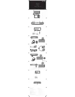
Output Configuration
Under normal operation there are four internal frequency
sources that may be routed via a programmable crosspoint
switch to any of the four programmable 7-bit output dividers.
The four sources are: reference, PLL1, PLL2, and PLL3. In
addition, many outputs have a unique capability for even
greater flexibility. The following is a description of each output.
CLKA’s output originates from the crosspoint switch and goes
through a programmable 7-bit post divider. The 7-bit post
divider derives its value from one of two programmable
registers. Each of the eight possible combinations of S0, S1,
S2 controls which of the two programmable registers is loaded
into CLKA’s 7-bit post divider. See the section
“General-Purpose Inputs” for more information.
CLKB’s output originates from the crosspoint switch and goes
through a programmable 7-bit post divider. The 7-bit post
divider derives its value from one of two programmable
registers. Each of the eight possible combinations of S0, S1,
and S2 controls which of the two programmable registers is
loaded into CLKA’s 7-bit post divider. See the section
“General-Purpose” Inputs for more information.
CLKC’s output originates from the crosspoint switch and goes
through a programmable 7-bit post divider. The 7-bit post
divider derives its value from one programmable register.
CLKD’s output originates from the crosspoint switch and goes
through a programmable 7-bit post divider. The 7-bit post
divider derives its value from one programmable register.
CLKE’s output originates from PLL1 and goes through a post
divider that may be programmed to /2, /3, or /4.
XBUF is simply the buffered reference.
The Clock outputs have been designed to drive a single point
load with a total lumped load capacitance of 15 pF. While
driving multiple loads is possible with the proper termination it
is generally not recommended.
Power Saving Features
The SHUTDOWN/OE input three-states the outputs when
pulled LOW. If system shutdown is enabled, a LOW on this pin
also shuts off the PLLs, counters, the reference oscillator, and
all other active components. The resulting current on the V
DD
pins will be less than 5
µ
A (typical). After leaving shutdown
mode, the PLLs will have to relock.
The S2/SUSPEND input can be configured to shut down a
customizable set of outputs and/or PLLs, when LOW. All PLLs
and any of the outputs can be shut off in nearly any combi-
nation. The only limitation is that if a PLL is shut off, all outputs
derived from it must also be shut off. Suspending a PLL shuts
off all associated logic, while suspending an output simply
forces a three-state condition.