7
Note 3: Only one host connection is supported at a time. USB
functionality will be disabled if host devices are connected to both
sides simultaneously.
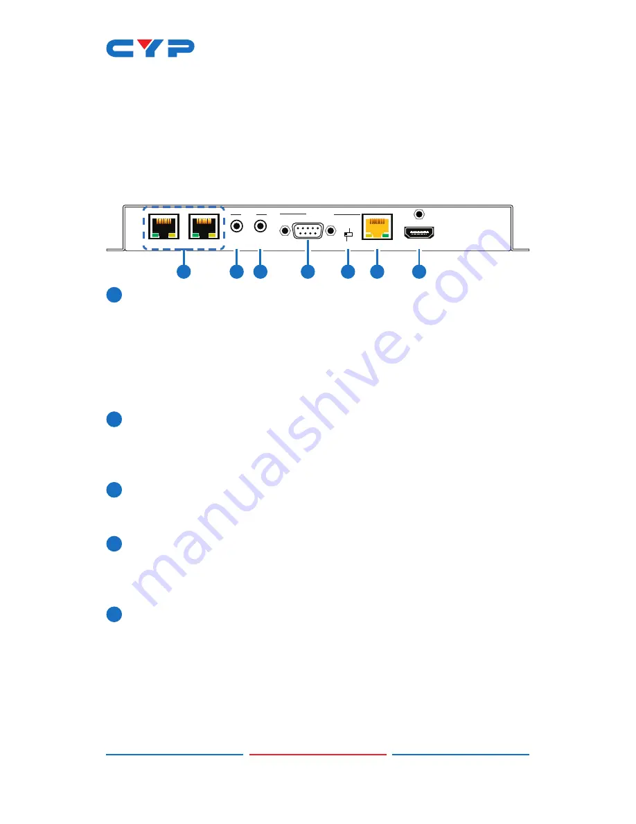
6.4 Receiver's Rear Panel
HDMI OUT
HDBaseT IN
LAN 2
LAN 1
BLASTER
EXTENDER
IR
2
1
BYPASS
RS-232
CONSOLE
1
2
3
4
5
6
7
1
LAN 1~2:
Connect to an Ethernet supporting device or to your
local network, as appropriate, to extend the network to both ends
of the HDBaseT connection.
Note: Connect only one Ethernet port from the HDBaseT
Transmitter/Receiver pair to the local network. Connecting multiple
ports to the same local network may result in a feedback loop and
cause the network to fail.
2
IR EXTENDER 1:
Connect to an IR Extender to extend the IR control
range of devices connected to the other end of the HDBaseT
connection. Ensure that the remote being used is within direct line-
of-sight of the IR Extender.
3
IR BLASTER 2:
Connect to the provided IR Blaster to transmit IR
signals from the other end of the HDBaseT connection to devices
within direct line-of-sight of the IR Blaster.
4
RS-232:
Connect to a PC, laptop or serial controllable device for
the extension of RS-232 signals between both ends of the HDBaseT
connection in "Bypass" mode, or for control this unit when in
"Console" mode.
5
CONSOLE/BYPASS:
This switch controls the operational mode of the
RS-232 port. When set to “Bypass”, RS-232 signals will be passed to
the connected Receiver. When set to “Console” the RS-232 port
will send commands directly to the Receiver.
Note: RS-232 bypass requires both the Transmitter and Receiver to
be set to “Bypass” mode. "Console" mode is currently reserved for
factory use only.
Содержание CH-1604RXD
Страница 2: ......
Страница 22: ......
Страница 23: ......
Страница 24: ...CYPRESS TECHNOLOGY CO LTD www cypress com tw ...


